Tutorial (Godot Engine v3 - GDScript) - Wave formations (scripted)!
 Tutorial

What Will I Learn?
Following on from yesterday's "concept" tutorial about Wave formations; which implemented Path2D and PathFollow2D manually. I will show you how to implement them in GDScript!
Here are three path types I'll explain how to form.
Note: the recording method records at 30fps
From learning these three, you should gain enough confidence to unleash your own patterns!
Assumptions
- You have installed Godot Engine v3.0
- You are familiar with GDScipt
You will
- Learn to create a 'Path' factory
- Learn how to specify a path (starting with a simple box)
- Learn how to add a Box path with a Curved edge
- Learn how to add a Figure of Eight path
Requirements
You must have installed Godot Engine v3.0.
All the code from this tutorial will be provided in a GitHub repository. I'll explain more about this, towards the end of the tutorial.
Create a 'Path' Factory
To simplify the creation of multiple Paths in my games, I've decided to use a Factory pattern. The factory will be responsible for:
- Creating the paths
- Adding them to the screen
- Clearing them after
By using a Factory, I can then write the code once and reuse for as many Paths as I require in my game.
The Factory will be created as a new Scene Instance, as a Node type and a bespoke script. The script will deliver these functions:
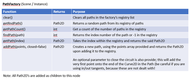
This will become very easy to understand, although will look a little daunting to those not used to this structured design,
if you aren't, you should explore the "Gang of Four" Object Oriented patterns. Although you don't need to be fully OO aware, it will aid your thinking. After all, they've been around for several decades and done me no harm!
Please:
- Create a new Project and Game Scene
- Create a secondary Scene and call it PathFactory
- Add a Node as the root node
- Add a script to the Node
Let's write some code:
extends Node
Extend the basic Node class
var paths = []
Declare our array to store the Path registry
func clear():
    for the path in paths:
        path.queue_free()
        paths.remove(path)
The first of our list of functions. This will get each path in the registry list, free it from being a child and then remove it from the registry. I.E. we'll clear down the list
func getRndPath():
    return paths[randi() % paths.size()]
The second function returns a random Path2D from the registry, based on the number in the list. This does not have any defensive coding for when it is empty; therefore if there is a potential of it being so, a condition to handle it
func getPathCount():
    return paths.size()
Next up is a function which returns the number of Paths in the registry
func findPath(path):
    return paths.find(path)
This function provides the capability of searching the registry and obtaining the integer index number for it is found (or -1 for not found)
func getPath(index):
    return paths[index]
This function will retrieve a Path2D from the registry, given its index. The last three functions may be used by another Script to loop through the entire registry; although in GDScript, you may directly use the Paths array instead!
From an OO viewpoint, I hate GDScript for some of its reduced constraints, but it does make life SO much easier! You have to write a lot less code, but I still find old habits hard to lose!
func addPath(points, closed=false):
    var curve = createCurve(points, closed)
    return createPath(curve)
The main function is the addPath which expects an array of points to be supplied and the flag toggled as to whether it is to add an additional point to close the circuit. This function calls two helper functions, the first to create the Curve2D based on the array of points and the second converts it to a Path2D before returning it.
func createCurve(points, closed=false):
    var curve = Curve2D.new()
    for point in points:
        var position = point[0]
        var inTan = (point[1] if point.size() > 1 else Vector2())
        var outTan = (point[2] if point.size() > 2 else Vector2())
        curve.add_point(position, inTan, outTan)
    if (closed):
        curve.add_point(curve.get_point_position(0))
    return curve
This function takes an array of points and converts them into a new Curve2D object.
- Initially create the new Curve2D object
- Loop through each point in the points array
- get the position of the point, which is assumed to be the first element of an embedded array
- get the 'In Tangent' point (see below), which will be the second element if the embedded array has 2 or more elements
- get the 'Out Tangent' point (see below), which will be the third element, if the embedded array has 3 elements
- add the new point to the Curve2D object
- once finished the loop, check if the closed flag is set and add the first point into the Curve2D at the end to close the circuit
- return the Curve2D
func createPath(curve):
    var path2D = Path2D.new()
    path2D.curve = curve
    paths.append(path2D)
    add_child(path2D)
    return path2D
This function receives the Curve2D, and then:
- creates the Path2D object
- sets the curve of the object to the value passed in
- adds the Path2D object to the registry
- adds the Path2D as a parent-child to this factory (so it will show)
- finally returns the Path2D
This factory Class Instance is fairly simple but offers many capabilities that can be used in games and extended on.
I hope from the description that you've gauged there are three parameters required to create a point in the Curve2D object. This is explained in the official documentation for the add_point method.
To recap:
- The first parameter is a Vector2 position point on the screen
- The second parameter (Vector2) is the first of two 'Control Points' for the line; this is the 'In Tangent'. I.E. it will influence the line from this point
- The third parameter (Vector2) is the 'Out Tangent'; i.e. it will influence the line as it reaches the next Point in the path
The 'Control Points' are the controls you should be familiar with in the previous tutorial. They are the handles from each point, that enable you to create curves!
If you've been paying attention in that tutorial as well as this, there are two parameters here, but in the editor, there is only one control. I ASSUME the editor takes care of both. In the code, we gain more flexibility OR I've missed a control somewhere!
I'm not going to explain what a Tangent Line is, but there are plenty of good articles.
When I get to the Curved Box example, I'll show and explain how I set these values and I believe you should start to understand them.
The points array is a multi-dimensional one, in the format of:
[
    [ Vector2(), Vector2(), Vector2()],  # First point, which is position, in tangent and out tangent
    [ Vector2(), Vector2(), Vector2()],  # Second point
    [ Vector2(), Vector2(), Vector2()]  # ..and so forth
]
Again, I'll explain these through examples below.
Add the PathFactory instance as a child in the Game Scene root:
Like so:
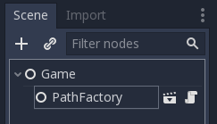
Let's now create our first path, which will be a simple box.
Create our first path (a simple box)
To keep things simple, let's create a path in the shape of a rectangular box and add followers to it!
I created a new Scene and added a root Node and named it BoxPath 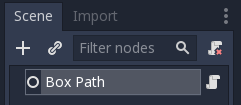
Then add the following script to it:
extends Node
Extend the base Node class
export (NodePath) var nodePathFactory = "../PathFactory"
export (int) var followerCount = 10
export (int) var followerGap = 32
export (bool) var closed = true
export (bool) var drawPathLine = false
export (Color) var pathColour = Color(0xffff00f0)
export (bool) var visible = false
A list of Node Inspector parameters that will allow a developer to alter its use:
- The first is the path to the PathFactory instance; given the factory will be used to construct the path
- The next two properties allow the number of followers and the gap on the path between them
- A flag is provided to determine whether the path is to be closed
- The next two parameters allow for the Path to be drawn as lines on the screen and the colour to use
- The final parameter is something I needed in the GitHub copy, because I will include all three Paths and I wanted to be able to hide them easily!
const FOLLOWER = preload("res://Followers/Follower.tscn")
The Follower scene is preloaded and ready to be instanced (see further down for the Follower code; but remember you will need to ensure you create the same path or change it here).
var path = [
    [Vector2(100, 100)],
    [Vector2(1820, 100)],
    [Vector2(1820, 980)],
    [Vector2(100, 980)]
]
This is the definition for the rectangular path (see below for more details; but note that the lines shall be straight, therefore the In and Out tangent settings have not been supplied
Try plotting the points on a bit of paper, as you should be able to figure this out for yourself! *Remember the screen resolution is set to 1920x1080 and I then enable 2D Scale in both Aspects
func _ready():
    if nodePathFactory != null:
        if visible:
            var path = generatePath()
            if drawPathLine:
                drawPathLine(path)
            addFollowers(path)
    else:
        print("Path to Factory Node not set! ", get_path())
        get_tree().quit()
This function starts when the node is ready. It:
- checks if the path to the PathFactory has been set
- if it has, check whether it is set visible
- if visible call the function to generate the path
- then check whether the path line should be drawn and show it if wanted
- finally, add the followers to the path
- otherwise output a message to the console and stop! Without the factory, the code will not work
func generatePath():
    return get_node(nodePathFactory).addPath(path, closed)
Find the PathFactory and call the addPath function, returning the Path2D back to the ready function
func drawPathLine(path):
    var line = Line2D.new()
    line.points = path.curve.get_baked_points()
    line.modulate = Color(pathColour)
    path.add_child(line)
Given the path line is required, create a Line2D object, assign its points along the Path2D route, set the desired colour and add the object as a child to the Path2D. The line will then appear, as if by magic.
func addFollowers(path):
    for i in range (followerCount):
        var follower = FOLLOWER.instance()
        follower.setInitOffset(i * -(followerGap))
        path.add_child(follower)
Loop for the desired number of followers, create a new Follower instance and set its initial offset to the desired gap (which is the item number * the gap size required; remembering to go to the back of the queue). Finally add the follower to the Path2D
Add your new Box Path instance to the Game Scene:
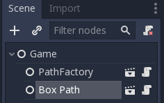
Clearly, the code wont work until you add the Follower. I created a new Scene in a sub folder of "/Follower/Follower.tscn":
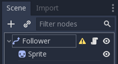
This is not too disimilar to the previous tutorial, but I have implemented it a tad differently, so please pay note:
- The PathFollower2D has been added with an additional script
- The same Sprite set-up has been added
NO AnimationPlayer has been added, instead, I've added a few lines in the PathFollower2D root node script. I've done this to demonstrate there are MANY different ways to achieve these solutions!
This is the code to add:
extends PathFollow2D
Extend the PathFollow2D class
func setInitOffset(value):
    offset = value
This function sets the initial offset along the path and is used by the Box Path code to set the poisition along the chain
func _process(delta):
    offset += 800 * delta
Instead of using the animation player, I've added a process function which will be called every frame. This moves the follower along the Offset (which is the total pixels in the path; rather than the Unit Offset which is a fractional value between 0 and 1). I've done this to show that Offset can be used to accurately control the velocity of the Sprite that is attached to this follower.
In my previous tutorial, I stated that I didn't see a need for the Offset property; I'm not too proud to admit that I was wrong! This is what I really need as I want to control the speed of my Invaders.
Please note though, for each follower object, the process function is called. This will be a lot more work for the engine, rather than if it were assigned to the AnimationPlayer; however, more flexibilty is provided. I plan to play around with these a little more in the 'Invaders' tutorial.
Now we have all the code we require, try running it!
... nothing should happen. Why?? Any ideas?
Check the properties of your Box Path in the Node Inspector:
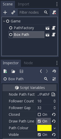
Ensure you have set it visible and set the other parameters. You should now see a train of sprites moving around the rectangle:
Try playing with the properites, including turning the line on off, the colour of it, closing the circuit and turning on the Debug 'view paths' option.
Before I move on, here's a diagram of the path array settings:
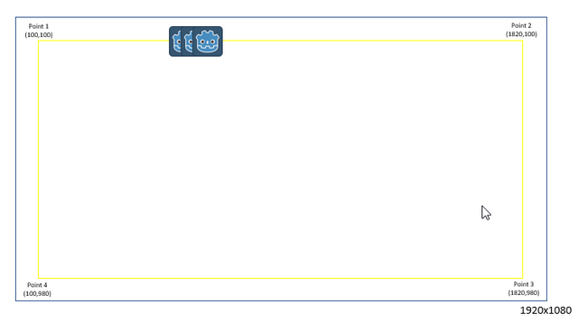
This should be fairly straight-forward to understand.
Create Curved Box Path
Believe it or not, creating the next example is MUCH easier! We simply need to change the Path array.
What I did was create a new Scene called Curved Box Path, added a Node as the root and then added a script, copying in the script from the Box Path example above.
I then changed the Path array to this:
var path = [
    [Vector2(50+100, 50)],
    [Vector2(1920-50-100, 50), Vector2(), Vector2(50, 0)],
    [Vector2(1920-50, 50 + 100), Vector2(0, -50)],
    [Vector2(1920-50, 1080 - 100 - 50), Vector2(), Vector2(0, 50)],
    [Vector2(1920-50-100, 1080 - 50), Vector2(50, 0)],
    [Vector2(50+100, 1080 - 50), Vector2(), Vector2(-50, 0)],
    [Vector2(50, 1080 - 100 - 50), Vector2(0, 50)],
    [Vector2(50, 100 + 50), Vector2(), Vector2(0, -50)],
    [Vector2(50+100, 50), Vector2(-50, 0)]
]
Whoa! That looks a lot scarier! I'll explain what the settings mean further down.
Let's run the example; ensuring the Inspector Properties are set to ensure it is visible after you add it as an Instance to the Game scene.
Moving nicely and we have curved corners!
The following is a diagram showing the 8 Positional points in the array (i.e. the first Vector2 in each line):
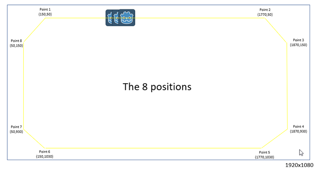
However, the In and Out Tangents have also been supplied, therefore those diaganol corners smooth out into curves. Let me show you from Point 2 to Point 3:
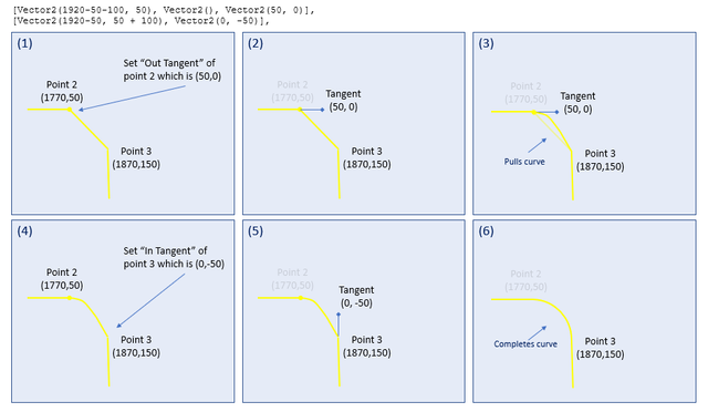
I hope I do this justice, because it isn't as easy as one would think to explain!
- Points 2 and 3 are shown; as per the snippet of Path array outside the diagram
- The third paramter for Point 2 is the "Out Tangent"; what I decided was to extend to the left by 50 pixels, which is the radius of the curve. The half way point between the x axis of Point 3, when added to Point 2's
- By setting the "Out Tangent" of Point 2, we end up with Half the curve we desire (try this in your environment! I.E. in Point 3, set the second parameter to (0,0)
- The "In Tangent" of Point 3 (which is the second parameter) is used to curve the second half of the line.
- The Tangent needs to pull upwards by 50 pixels, to ensure it's Y axis is half way to Point 2's.
- The full curve then appears
This logic is then applied in a similar fashion to each corner.
Pulling on the correct axis between the points.
Create a Figure of Eight Path
Again, adding a figure of eight is as simple as changing the Path array to this:
var path = [
    [Vector2(960, 540)],
    [Vector2(1440, 200), Vector2(), Vector2(480,-340)],
    [Vector2(1440, 880), Vector2(480,340)],
    [Vector2(960, 540)],
    [Vector2(480, 200), Vector2(), Vector2(-480, -340)],
    [Vector2(480, 880), Vector2(-480, 340)],
    [Vector2(960, 540)]
]
The path:
- starts in the middle of the screen
- stretches up-right
- then joins a point immediately below it, using the Out Tangent of point2 and In Tangent of Point 3
- the path then stretches all the way up-left
- it then joins a point immediately below it, using tangents to curve the end again
- finally, it joins the centre point
As can be seen here:
Finally
This tutorial has been significantly harder to write for me. I'm 'NOT' quite sure if I've explained it well or not.
I've not addresses the random patterns, as promised in my return post! I.E. the one with the invaders whizzing around. I've done so, because I feel that is more specific to the Invaders tutorial and the fact that I'm now whacked from writing this!
Please do comment and ask questions! I'm more than happy to interact with you. If it isn't right, i've got a few days to fix it; so please ask!
Sample Project
I hope you've read through this Tutorial, as it will provide you with the hands-on skills that you simply can't learn from downloading the sample set of code.
However, for those wanting the code, please download from GitHub.
You should then Import the "Wave formations (part 2)" folder into Godot Engine.
There are three instance Nodes:
- Box Path
- Curved Box Path
- Figure 8 Path
You can show/hide these by changing the Visible property found in the Node Inspector window (the normal Visible toggle will not be available, because I'm not extending a Node2D class!)
Other Tutorials
Beginners
Competent
Expert
Posted on Utopian.io - Rewarding Open Source Contributors
Thanks for the contribution it has been approved.
Need help? Write a ticket on https://support.utopian.io.
Chat with us on Discord.
[utopian-moderator]
Thanks Deathwing for approving, much appreciated. I just want to gently point out that you marked the scoring that I provide no resources or Github, yet there is a section near the end that provides that; therefore that should have been marked yes.
Hey @sp33dy I am @utopian-io. I have just upvoted you!
Achievements
Utopian Witness!
Participate on Discord. Lets GROW TOGETHER!
Up-vote this comment to grow my power and help Open Source contributions like this one. Want to chat? Join me on Discord https://discord.gg/Pc8HG9x
Yay! This has finally made it into the Utopian-io system. If you are on there, I would really appreciate you using the new scoring system, as that will help guide me to what you would like!
https://www.youtube.com/paulbegley34
Resteemed your article. This article was resteemed because you are part of the New Steemians project. You can learn more about it here: https://steemit.com/introduceyourself/@gaman/new-steemians-project-launch