A Question Guys - Electrical Expertise Required - DIY - [SH2OMI]
Hello fellow Meisters,
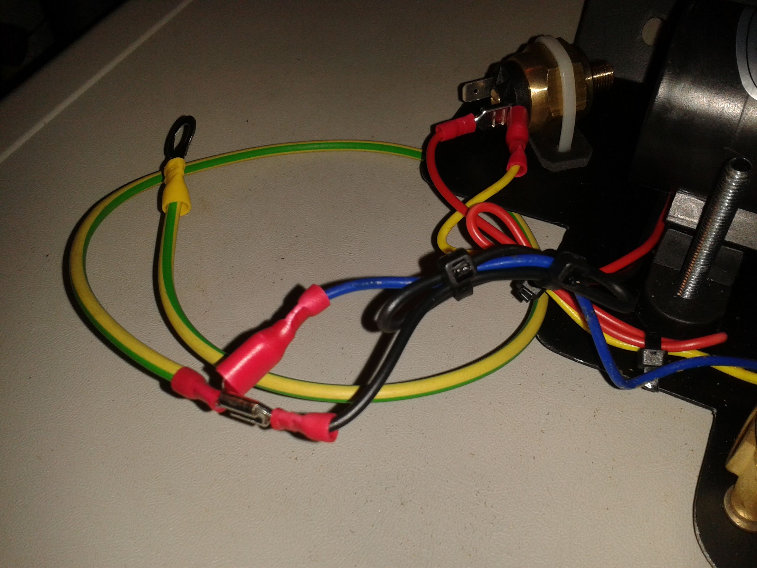
For those of you following my latest project (Stealth Water Methanol Injection system) for my little Skoda, you'll probably be aware that I'm getting beyond the theory and design stages and into the construction phase. In my last post, I showed you guys the main components (water pump, solenoid valve & boost switch) mounted to a bespoke aluminium plate. On this unit, you can clearly see an earth strap which takes the negative feed from the pump & valve.
In the cabin I will be taking a 12v line from either the fuse box or the cigar lighter to power the system and have it wired through the firewall. Now, I intend to add an activation switch, along with a 'system ready' LED and an 'active' LED placed somewhere on/in the dashboard.
The question is folks:
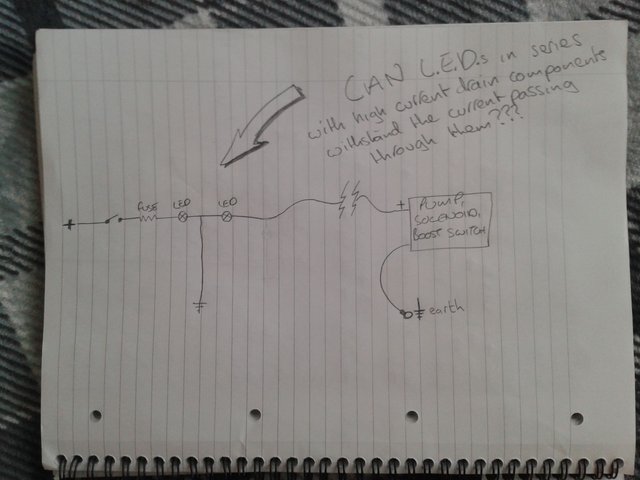
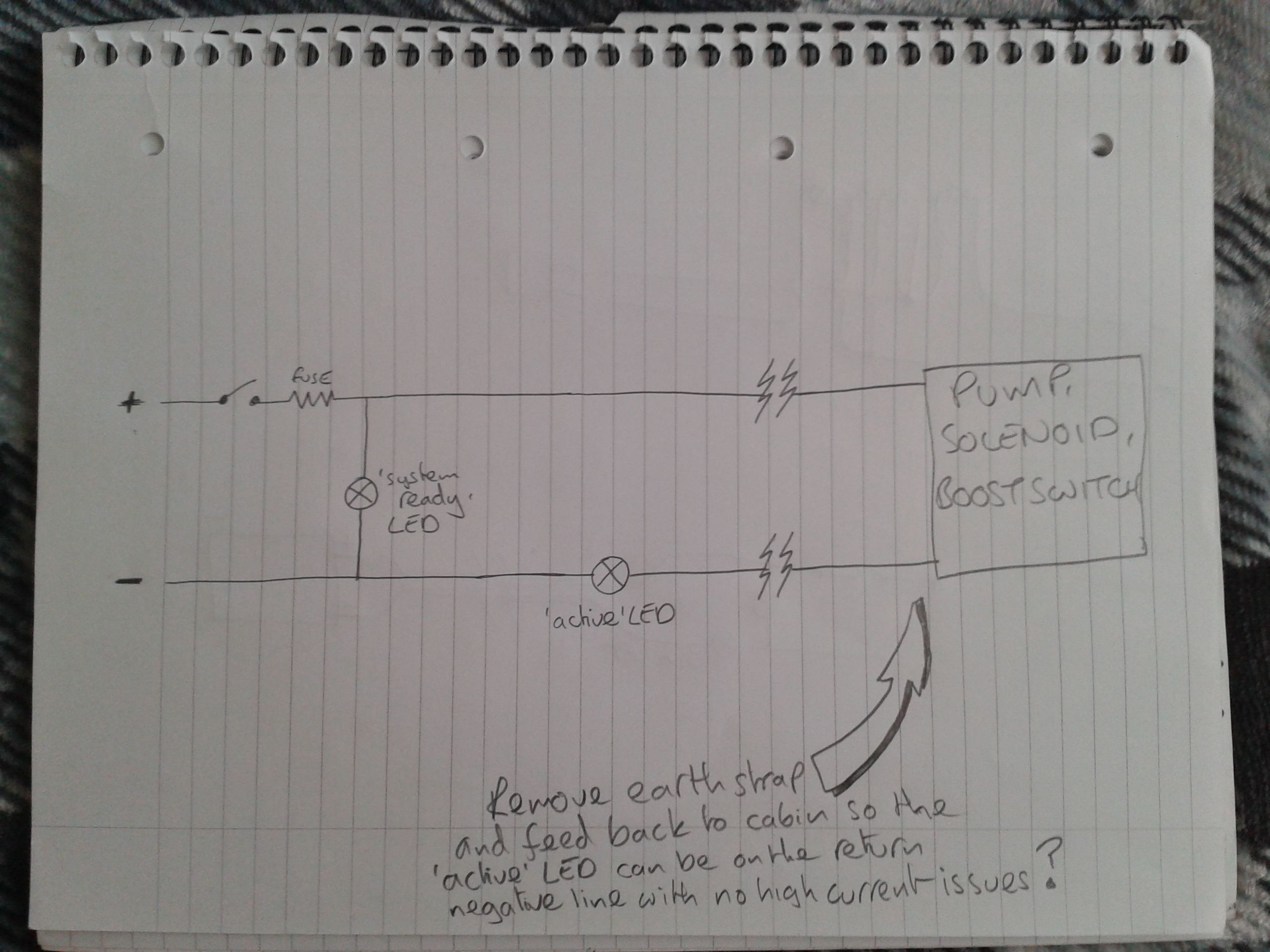
In order to keep things simple and the use of wiring to a minimal, can these LEDs (specifically the 'active' LED) run in series with the pump and valve even though there will be a relatively high current passing through them or should I ditch the earth strap and run a wire back to the cabin, running them in parallel with the 'active' LED on negative side negating the potentially damaging current?
Sorry if I haven't explained myself properly folks, hopefully the images below will make more sense.
[so basically either this....]
[or this?]
I greatly appreciate any advice and/or recommendations regarding this issue as my electrical knowledge is very rusty these days.
Many thanks,
Robster.
My previous posts on this project:
https://steemit.com/cars/@eggmeister/increasing-power-diy-water-methanol-kit-sketches-and-musings
https://steemit.com/cars/@eggmeister/more-power-water-methanol-injection-product-placement
https://steemit.com/cars/@eggmeister/sh2omi-should-i-diy-stealth-water-methanol-injection-system

Hi Rob, I have little (or none) technical skills for this.
But I would suggest taking it over to the #workshop channel on the Homesteaders Discord.
There are some handy tech people there like @greenacrehome
Ahh, that's brilliant @pennsif, greatly appreciated :)
I've managed to get the brain-freeze to ease and redone the design (though in principle it's the same as diagram #2). I'm trying to keep the design super simple (though you wouldn't think it by how I've struggled today lol) and inexpensive. So when things are at that point, I will quick-test the below set up and all being well, implement it. If it goes pear-shaped then I will follow your advice and give the Discord channel a go :)
Many thanks again,
Rob.
👍
Dearest Hubby, who majored in Electrical Engineering and who is a big fan of 70's muscle cars weighed in with this:
Many thanks @re-engineer, I've redesigned the circuit using a relay to drive the pump and solenoid so hopefully all is sorted now :)
I'll be posting new schematic of the circuit very soon.
Thanks again,
Robster.
Excellent! Look forward to seeing it! 👍
Hi, can’t you just use a relay to activate the pump so the switch and leds don’t have to subjected to the higher amps. I have an air pump for my catalyser that activates that way, only for emissions testing 😁 otherwise the cat and pump are on the shelf. 😂
Of course, why didn't I think of that lol.
Just to put my mind at ease though, would the 2nd diagram still be quite feasible/reliable/safe?
This just goes to show how I can't seem to get my head around simple circuits any more.
I've just drawn this revision based on adding a relay:
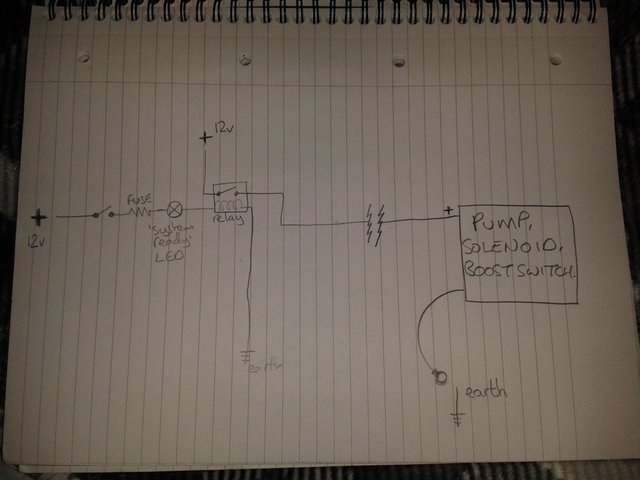
But it looks like I'll still need a return back to the cabin for the 'active' LED to be fitted. I guess I could install relay between boost switch and pump/valve but then I'll again need a return line for the same LED.
I'm getting really confused with this now :(
Probably over-complicating things lol.
HELP!!!
Urgh! Isn’t there a switch can handle that with the lamps instead? I’m no electronics genius!
I don't know..............
............ my brain is going to explode!!!
Aaarrghh!!!!
I think I need a beer!!!
Haha 😂 🍺 cheers!
Cheers back at ya ;)
Like @jasonwhite said use some relays. I may miss some detail but power to switch send power to light(led) ground and to you boost switch, boost switch send power to the relay the will power your pump.
Hi Chris, I'm starting to get my head around it now. I get easily flustered these days ;) Old age lol
Much appreciated, I will do some revisions on paper.
Cheers,
Rob.