제로부터 시작하는 극한의 아두이노 DIY생활 - ADC3
안녕하세요! Jimae입니다.
자 오늘은 저번에 이어서 한번 시작해 보겠습니다.
바로 하드웨어 구성을 어떻게 해야하느냐!!
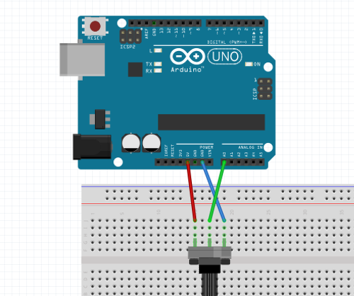
이렇게 연결하시면 됩니다.
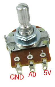
두 이미지가 GND, 5V Pin이 맞지 않은대... 별상관없습니다.
이것은 가변저항이기 때문에 극성이 없어요.
가운데 Pin만 A0에 꼭연결하시면 됩니다.
이 상태에서 전원을 연결하고! 가변저항을 시계방향 또는 시계반대방향으로 돌려주면 됩니다.
아주 간단하죠?
자 그러면 소프트 웨어를 봅시다.
const int analogInPin = A0;  // Analog input pin that the potentiometer is attached to

void setup() {
  // initialize serial communications at 9600 bps:
  Serial.begin(9600);
}

void loop() {
  int sensorValue = 0;        // value read from the pot
  // read the analog in value:
  sensorValue = analogRead(analogInPin);

  // print the results to the Serial Monitor:
  Serial.print("sensor = ");
  Serial.print(sensorValue);

  // wait 2 milliseconds before the next loop for the analog-to-digital
  // converter to settle after the last reading:
  delay(2);
}
A0의 Pin의 ADC 값을 읽어서 예전에 배운 시리얼통신을 통해서 PC 화면으로 그값을 뿌려주는 프로그램입니다.
sensorValue = analogRead(analogInPin);
이 함수가 ADC 값을 읽어서 sensorValue 변수에 그값을 저장하는 용도이구요.
analogInPin 의값은 A0 입니다.
delay(2);
딜레이가 2ms 정도 되는대 엄청 빠를거에요. 그래서
delay(500);
딜레이 값을 500ms 값으로 변경을 해주면 0.5초당 ADC 값을 PC화면으로 뿌려줄 것입니다.
const int analogInPin = A0;  // Analog input pin that the potentiometer is attached to

void setup() {
  // initialize serial communications at 9600 bps:
  Serial.begin(9600);
}

void loop() {
  int sensorValue = 0;        // value read from the pot
  // read the analog in value:
  sensorValue = analogRead(analogInPin);

  // print the results to the Serial Monitor:
  Serial.print("sensor = ");
  Serial.print(sensorValue);

  // wait 2 milliseconds before the next loop for the analog-to-digital
  // converter to settle after the last reading:
  delay(500);
}
최종적으로 이렇게 되겠네요.
자 그럼 다음시간에 한번 실제로 구성을 해서 Test를 해보겠습니다.
다들 좋은하루 되세요.
제로부터 시작하는 극한의 아두이노 DIY생활 - ADC1
제로부터 시작하는 극한의 아두이노 DIY생활 - ADC2
Upvoted! Thank you for supporting witness @jswit.