Empowering ourselves with fundition: Advanced Physics (Simplified) #1
Good day, Steemian. It's a pleasure being on this great platform once again. My fellow steemian, in case you have not yet heard of "fundition", it's a crowdfunding program aiming to make the world a better place, and impact the daily life of many people, communities and in the end all of us. You can get to know more about fundition here.
Join Fundition - A community with heart based giving at its core
The Second Activity is about Empowering Our-self!
"Education is the most powerful weapon to change the world".
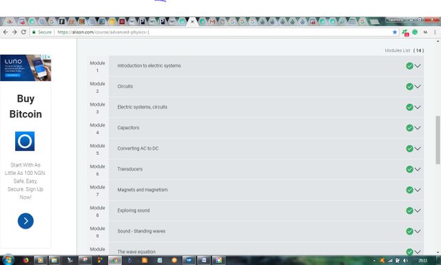
Second Activity will be Educative. We want you to finish one course on Alison.com. You can choose any course that you may like, it has to be minimum of three hours. Whatever you learn from the course, we want you to write a post on Steemit summarizing what was the course all about , and what you have learnt so far. Give the name of the course and the link too, also a screenshot that you have finished the course. And lastly using the tag of "funditian". As a reward you have a chance to get upvote from Fundition. The Deadline for it is until next hangout - Good Luck!
To read more about the "quoted" words above, here's the link
So, here's a post of mine titled Empowering Our-self: Advanced physics (simplified) part 1 in response to the above-quoted word from fundition.
Let's get started, the course "Advanced Physics 1" on Alison.com covers 13 chapters ranging from Introduction to electric systems, Circuits, Electric systems-circuits, Capacitors, Converting AC to DC, Transducers, Magnets and Magnetism, Exploring sound, Sound-Standing waves, The wave equation, Sound diffraction, Intensity of sound, and to Speed of sound.
We can see they are a hell of a topic and I've got to summarize on what I've read and understood in all of them and also what I've gained so far. So, by starting with the first:
1. INTRODUCTION TO ELECTRIC SYSTEMS
This chapter explains topics such as electric current, electric charge, voltage, resistance, work done and power.
It made us know that electric current consists of moving charges or electrons from one atom to the other in a conductor. Naturally, in a circuit, electrons flow from the negative terminal to that of the positive terminal of a power supply. A circuit is the path followed by the flow of electric current. Since the earlier scientists didn't know whether electric current involves the movement of either the positive or negative charge in a circuit, they now made use of a convention that says positive charge flows from the positive terminal of a power supply to that of a negative terminal in a circuit, which is a contradiction to how electric current really behaves. Despite the err in this convection, it's only the direction of current and the magnitude of the voltage that's affected.
Electric charges can easily be measured in Coulombs, while current is measured in amperes. 1 ampere is a current of one coulomb of charge per second and is measured using an ammeter. An electric current can be mathematically written as:
Q=It; where Q is the charge in coulombs, I is the current in Ampere and t is the time in seconds.
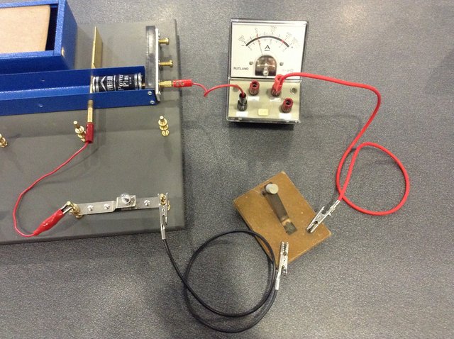
A Voltage, which is also referred to as the potential difference (p.d) is the work done by moving one coulomb of charge from one point in a battery to the other. Its unit is the volts and measured using a voltmeter which must be placed in parallel on either side of the circuit.
V=E/Q; where V is the voltage in volts (v), E is the energy change in Joules (J), and Q is the charge in coulombs (C)
or V=W/Q where W is the work done in Joules (J).
Resistance can be defined as the opposition to the flow of charges (electrons) or current. Its unit is the ohms. Materials through which electric current can flow easily (less resistance) are known as conductors in which all metals are notable examples. Insulators are those materials that do not allow electric currents to flow easily through them (high resistance), examples are ceramics and plastics.
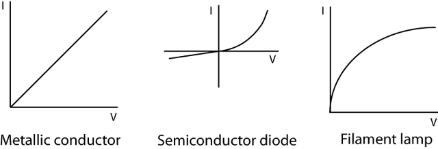
A German scientist by the name of George Ohm conducted some series of experiment (later known as Ohm's law) in which he sought to investigate the relationship between the current passing through a metallic wire and the potential difference across its ends. He discovered that there is a linear relationship between such a current and the potential difference i.e as the voltage applied to the wire is increasing so also is the amount of current flowing through it, and the materials exhibiting such property are called Ohmic conductors e.g. A graph of an ohmic device is always a straight line graph since the voltage applied increases linearly as the current increases i.e:
V=IR, where V is the voltage in volts (v), I is the current in amps (A) and R is the resistance in ohms. The materials that exhibit non-linear changes in the current flowing through them when the applied voltage is altered are known as Non-ohmic conductors e.g tungsten.
Electrical Workdone: work is done when electricity flows from one point to another of different potential. It can also show how much electrical energy is converted to other forms of energy. If Q coulombs of electricity flows between the two points whose potential difference is V volts, then the Work done (W)is given by:
W=VQ where W is the work done (J), V is the voltage (v) and Q is the charge (C) and by substituting Q=It from above, then the work done becomes:
W = VQ = VIt
Power can be defined as the amount of joules of energy consumed in one second. It can also be defined as the rate of doing work. It is also the amount of electrical work done per second.
i.e Power = Energy/time.
P = E/t = W/t;
and by substituting W = VIt from above, hence;
P = VIt/t = VI;
where P is the power in watts (W), V isthe voltage in volts (v) and I is the current in amps (A).
2. CIRCUITS
This chapter comprises topics such as The series circuit, Parallel circuit, and AC circuits.
[A simple diagram of an electric circuit created by photoshop CC BY-SA 3.0 Unported]
The Series circuit is a type of an electric circuit that has all its elements joined to one another such that the same current flows through them all, i.e:
I (total) = I1 = I2 = I3 = .....,
and the equivalent voltage in such a circuit is the sum of all the individual voltages in the circuit, i.e :
V (supply) = V1 + V2 + V3 + ....., and this is because any coulomb of charge that must pass through the circuit from the battery must also pass through each item in the circuit thereby dropping some of its energy at each load. From this, we can then infer that the total resistance is also the sum of the individual resistance of each item in the circuit, i.e:
R (total) = R1 + R2 + R3 + ....
Parallel circuit is a type of circuit where its elements are arranged side by side such that their corresponding ends join together at two common junctions. Unlike in series circuit, any coulomb of charge leaving the battery will either pass through one load or the other; i.e in a parallel circuit, there are several ways in which electricity can flow through. In such an arrangement, the potential difference across it is the same but the current flowing through is different. The resistance in a parallel circuit is considerably less compared to that of the series circuit. What I'm saying, in essence, is that in a parallel circuit:
I(total) = I1 + I2 + I3 + ....,
V(supply) = V1 = V2 = V3 = ...., and
1/R(total) =1/R1 + 1/R2 + 1/R3 + ...
AC Circuits
AC circuits are circuits through which an "alternating current" flows. Such circuits are used extensively in power transmission, radio and television.
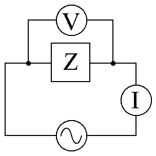
The electric power supplied to all residential areas is in the form of an AC. This is commonly called a 240volt supply. The value quoted is misleading as it implies that the voltage has a steady voltage, which it does not. In fact, the voltage varies between + 339 volts and -339 volts. The direction of the current changes twice per cycle. Since the supply has a frequency of 50 hertz, the period for one cycle is 1/f which is 1/50 = 0.02 seconds.
In calculation regarding AC circuits, we make use of the term rms which means (root mean square). The root-mean-square value of a current, which is also the effective value of the current is defined as that steady current which will develop the same quantity of heat in the same time and same resistance and is mathematically written as;
Irms = I(nought)/√2 = 0.7071 I(nought). Same rule applies to the Vrms too.
3. WORKED EXAMPLE ON CIRCUIT SYSTEM (SERIES AND PARALLEL)
A p.d of 24V from a battery is applied to a network of resistors below, (i) determine the total resistance in the circuit. (ii) what is the current in the 8 ohms resistor? (iii) what is the p.d across the parallel network?
.jpg)
[A freehand circuit diagram drawn by me, showing network of resistors]
Solution
(i) Let R1 be the combined resistance of 6 ohms and 12 ohms which are in parallel; thus,
1/R1 = 1/6 + 1/12 = 3/12
R1 = 12/3 = 4 ohms.
Then, the total resistance in the circuit is given as;
R = R1 + 8 ohms = 4 + 8 = 12 ohms.
(ii)Current (I) in the circuit is given as V/R = 24/12 = 2 amperes.
This is also the same current flowing through the 8 ohms resistor.
(iii) P.d across the parallel network is given as;
V = I × R1 = 2 × 4 = 8V
4. CAPACITORS
A Capacitor, Source: DMGualtieri, CC BY-SA 3.0 Unported
A Capacitor is any pair of conductors separated by an insulating material that can store electric charges or electrical energy. Generally, capacitors are used to store electric charges. They are also used in a situation whereby electricity is needed to be temporarily stored and later released later. They can also be used alongside an electric motor (e.g such in electric fans and Air-conditioner) to give an electrical spark to surmount the friction present to turn the motor because as soon as the motor is running, less current is needed to keep it moving.
.jpg)
.jpg)
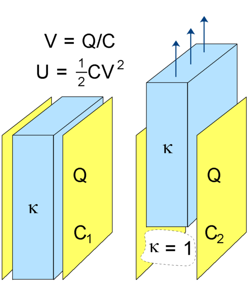
The Capacitance (C) of a capacitor is defined as the ratio of the charge Q on either plates or conductors to the potential difference V between them. That is, C = Q/V.
The unit of the capacitance is the Farad. There are also sub-divisions of the unit like microfarad [10^(-6)] and picofarad [10^(-9)]. The capacitance of a capacitor depends on some factors such as the surface area of the plates, the distance separating the plates and the nature of the insulating material between the plates. Basically, the capacitance increases with the area between the plates, decreases with increasing distance, and increases with dielectric constant.
Charging a Capacitor
From my definition of electric current above, as the flow of electrons from the negative terminal of a power supply to that of its positive terminal, so also is the charging principle of a capacitor. Capacitors can be charged by connecting the initially uncharged plates of the capacitor (let's say plate A and plate B) to a battery, this will thereby allow electrons to flow from the negative terminal of the battery. The electrons will then begin to pile up on plate A and develop a negative charge on the plate A. At the same time, the positive terminal of the battery will attract electrons from plate B also leaving the plate B with a positive charge.
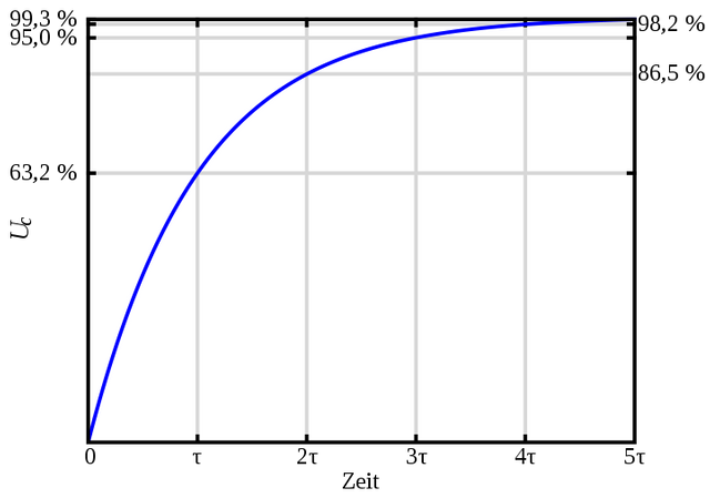
The time constant
Worked example
Calculate the time constant for the circuit shown below and how long would it take to fully charge the capacitor?
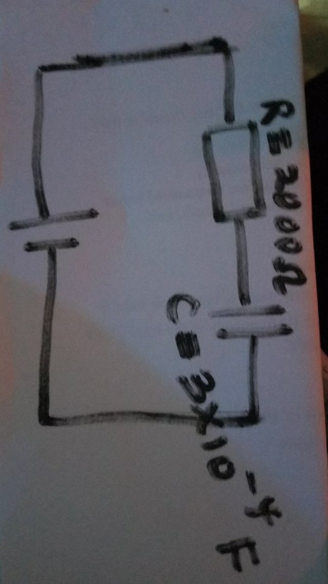
Solution
τ = RC = 2000 × 3 × 10^(-4)
τ = 6 × 10^(-1) = 0.6 seconds.
Since it takes five time-constants (i.e 5τ) to fully charge a capacitor, then it would take this capacitor (0.6 × 5) or 3 seconds to be fully charged.
Discharging a capacitor
We can remember from above, that as long as a battery is connected to a capacitor, it will always be fully charged i.e at a voltage that corresponds to the supply where no current is flowing. A capacitor will remain fully charged in as much as the battery is still connected. So, then to discharge a capacitor, one needs to disconnect the battery which is its only source of power.
CONCLUSION
In summary, the course teaches and explains on several physics topics as written at the beginning of this post. I was only able to write on electric systems, circuit, workings on circuits, and capacitors so as not to make the article too voluminous to read, though I've read through all the topics. That's the reason why I referred this post as the part 1. I'll still be writing on the remaining topics in my subsequent posts. I really learnt a lot from this course which is evident in the summary of what I've written above concerning electric circuits and current as a whole. I also got to know more on how to charge and discharge a capacitor.
Thanks for reading!
References
University Basic Physics, Revised Edition, by Ajayi J. O (Ph.D) pg 155, 162 and 164.
New School Physics for Senior Secondary Schools, 10th Edition, by Ayankoha M. W (Ph.D), pg 77-80 and pg 454

Resteemed your article. This article was resteemed because you are part of the New Steemians project. You can learn more about it here: https://steemit.com/introduceyourself/@gaman/new-steemians-project-launch
Hello there @emperorhassy,
Thank you for taking part in our Activity,spreading and learning with Fundition. We hope you enjoyed your course and learnt something. And also the ones that are reading it, got some great points from your great content.
Learn more about Fundition by reading our purplepaper
Join a community with heart based giving at its core
Congratulations @emperorhassy! You have completed the following achievement on Steemit and have been rewarded with new badge(s) :
Click on the badge to view your Board of Honor.
If you no longer want to receive notifications, reply to this comment with the word
STOPTo support your work, I also upvoted your post!
Do not miss the last post from @steemitboard:
SteemitBoard World Cup Contest - Play-off for third result
Participate in the SteemitBoard World Cup Contest!
Collect World Cup badges and win free SBD
Support the Gold Sponsors of the contest: @good-karma and @lukestokes
Congratulations! This post has been upvoted from the communal account, @minnowsupport, by emperorhassy from the Minnow Support Project. It's a witness project run by aggroed, ausbitbank, teamsteem, theprophet0, someguy123, neoxian, followbtcnews, and netuoso. The goal is to help Steemit grow by supporting Minnows. Please find us at the Peace, Abundance, and Liberty Network (PALnet) Discord Channel. It's a completely public and open space to all members of the Steemit community who voluntarily choose to be there.
If you would like to delegate to the Minnow Support Project you can do so by clicking on the following links: 50SP, 100SP, 250SP, 500SP, 1000SP, 5000SP.
Be sure to leave at least 50SP undelegated on your account.
This post has been voted on by the steemstem curation team and voting trail.
There is more to SteemSTEM than just writing posts, check here for some more tips on being a community member. You can also join our discord here to get to know the rest of the community!
Hi @emperorhassy!
Your post was upvoted by utopian.io in cooperation with steemstem - supporting knowledge, innovation and technological advancement on the Steem Blockchain.
Contribute to Open Source with utopian.io
Learn how to contribute on our website and join the new open source economy.
Want to chat? Join the Utopian Community on Discord https://discord.gg/h52nFrV