Fiber Optic Splicing Process
What Will I Learn?
This article will serve as a tutorial for scientist and students to splice the common fibers. The tasks to be done during splicing process are listed below.
- Stripping process
- Cleaving process
- Placing the fiber into the splicer machine process
- Parameters for splicing process
- Checking the quality of the splice
- References
- Future Works
Requirements
The requirements to be needed during splicing process are listed below.
- Two pieces of fibers (cladding size is 125-μm - similar to telecom fibers).
- A stripper to strip the coating parts of the fibers.
- A bottle of propanol to clean the unstripped part of the fibers.
- A cleaver to cleave (cut) tip of fibers with an angle 0.
- A splicer to combine these two fibers (FUJIKURA FSM-50S is used).
- A source to check the quality of the splice.
Difficulty
Intermediate
1-General Information About Fibers
Generally, a fiber [1] consists of a core, a cladding and a coating parts. Because of refractive difference between cladding and core part, the light is transmitted into the core by using "total internal reflection (TIR) phenomena" [2]. The refractive index difference is almost 5x10⁻⁴ (nclad < ncore). According to Snell's Law [3], the light goes into core can be reflected from the surface of the cladding part up to critical angle. If light reflects much more than critical angle then light goes out from the fiber and this means loss. Therefore, while splicing two fibers, the entrance angle is important. Actually this is about numerical aperture (NA) [4] of the fiber which means that the existance angle of the light form the tip of fiber. In this article, we will use two fibers which have same NA due to decrease the loss. For different NA fibers splicing method will be given in the next articles.
Coating part is the protective part of the fibers from the environmental effects such as dust, touching, mechanical, heat etc. For splicing the coating part is not important but when we splice double-clad fibers we need to recoat the unstripped part and the coating part will be important that kind of splices.
2- Stripping process
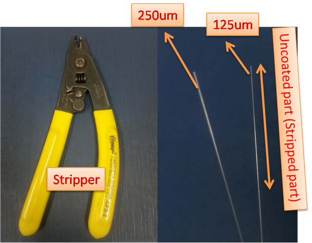
For telecom type fibers, the coating part has a 250μm diameter, the cladding part has a 125μm diameter and the core part has 6μm diameter. The coating part is made by silicon material and the melting temperature is almost 2000C besides, the cladding and core part is made by SiO2 and the melting temperature goes upto 20000C. Therefore, to combine the fibers core to core we need to strip the coating part of the fibers. The stripper and coated and uncoated fibers are seen in the below figure.
Figure-1: The stripper and coated and uncoated fibers
2- Cleaving process
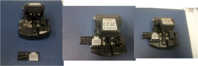
After stripping the 2-3 cm coating part of the fibers, we need to cleave them with an almost perfectly "0" angle. Before cleaving we need to clean these uncoated parts by a propanol (quick evaporation speciality) not to burn the fibers due to dusty particle, while splicing. This "0" angle is so important to combine the fibers without excess loss. If the fibers cannot cleaved with "0" angle then the combination will be bad and this splice point will give excess loss. Why this splice without a "0" angle tip gives excess loss is that the light goes out from the input fiber with a different angle (higher tahn critical angle) to the other fiber and this causes loss. The cleaver and cleaved fibers are seen in the below figure.
Figure-2: Left-The cleaver and holder with fiber, Middle-Placed the holder into cleaver, Right-Cleaved fiber with "0" angle.
3- Placing the fiber into the splicer machine process
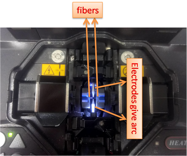
We ready our two fibers to combine by using splicer machine. Before explaining the placing the fibers into the splicer machine, we want to explain how the splicer machine works. Splicer machine is a device to combine the fibers by using arc which turns to heat and melt the tip of the fibers and after arcing the device combines two fibers by using overlap feature. Why arc fusion is used is that, to melting 1-2μm distance, you need to use arc fusion. For example, if we heat the fiber with a lighter, you cannot control the size the lighter output. Therefore, almost all splicer are use arc fusion. There a re some splicers which use filament also. The placing the fiber into the splicer machine are seen in the below figure.
Figure-3: Placing the fiber into the splicer machine
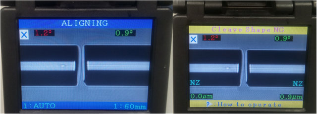
For general splicing [5], the processes into the device is given in the below:
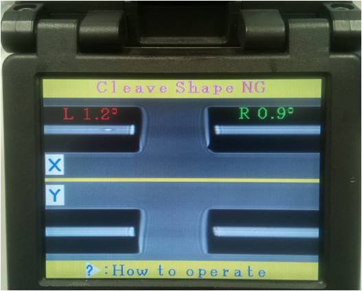
- Checking the angle of tip of fiber. There is a limit (adjustable) and if the angles of the tip of fiber is higher than this limit gives a warning.
Figure-4: Cleave limit error
- Giving a clean arc to clean the dusty particle. This clean arc is giving by a low power so it does not melt the fibers
- Adjusting the fibers core to core or clad to clad (usually this kind of splicers use clad to clad due to small core size) to combine two fibers exactly core to core.
Figure-5: Left-Before alignment, Right-After alingment (clad to clad)
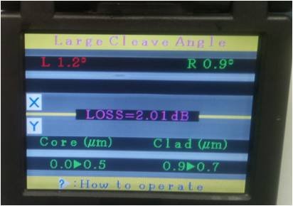
- Giving arc, and then overlap while arcing.
Figure-6: After splicing process, gives a loss message.
- Proof testing by stretching the fibers in the horizontal direction. This is optional.
4- Parameters for splicing process
Although there are lots of parameters for splicing, for telecom fibers (common splice) we need to revise some of them:
- Cleave limit: This is optional but if you do not want to proceed with an larger cleave angle, you can adjust this parameter.
- Arc Power: This parameter is needed to adjust the heat of the arc. This is really important not to damage the fibers.
- Arc Time: This parameter and arc power is depend on each other. You can think these two parameters as arc power defines the slope of the melting, arc time defines the time of melting.
- Cleaning Arc: This parameter is burns the dusty particle which cannot be cleaned in the process of cleaning uncoated parts of fibers. This should be low as possible as not to damage for the tip of fibers.
- Rearc Time: For common splice this is not needed too much but if you can control the power of the source then this parameter will helps you add an additional arc to the splice point.
5- Checking the quality of the splice
At the end of the splice, you need to check the quality of the splicing. To do that you need a source and a powermeter to check the optical power of the light. The source must be compatible with the fibers because to calculate the splice loss, we need to be sure that there is no other losses such as insertion loss of fiber, mechanical loss etc.
According to results you can calculate the loss in "dB" which is common for fiber optic technology. The formula is below:
αdB = -10*log10(PT/P0)
α - the loss , P0 - the power level of the light at the input of a fiber of length L, P T - the transmitted power of the light
6- References
Image and Video Source: All videos and images use in this tutorial is recorded and captured by the author. Otherwise, it is specified in the text.
7- Future Works
We will try to give details about fiber optic components to explain what is ULTRAFAST FIBER OPTICS.
If you enjoyed this post, feel free to Upvote, Follow and Resteem.
Have a curious day, Steemians....
Posted on Utopian.io - Rewarding Open Source Contributors
Your contribution cannot be approved because it does not refer to or relate to an open-source repository. See here for a definition of "open-source."
Utopian.io isn't the place for this kind of tutorials, so I recommend you read the rules and the FAQ so you better understand what is and isn't an acceptable contribution.
You can contact us on Discord.
[utopian-moderator]
Thanks for your warning. I misunderstood the concept.
Congratulations! This post has been upvoted from the communal account, @minnowsupport, by onderakcaalan from the Minnow Support Project. It's a witness project run by aggroed, ausbitbank, teamsteem, theprophet0, someguy123, neoxian, followbtcnews, and netuoso. The goal is to help Steemit grow by supporting Minnows. Please find us at the Peace, Abundance, and Liberty Network (PALnet) Discord Channel. It's a completely public and open space to all members of the Steemit community who voluntarily choose to be there.
If you would like to delegate to the Minnow Support Project you can do so by clicking on the following links: 50SP, 100SP, 250SP, 500SP, 1000SP, 5000SP.
Be sure to leave at least 50SP undelegated on your account.
Sneaky Ninja Attack! You have just been defended with a 5.07% upvote!
I was summoned by onderakcaalan. I have done their bidding and now I will vanish…
woosh
P.S. If you or anyone you know has been a victim of @grumpycat please know that he has been harming people throughout Sōsharumedia (ソーシャルメディア). Stealing the service that I (and other bots) have provided them and hiding behind a facade of stopping bid bot abuse which he clearly has no interest in.
Sneaky Ninja is a very responsible bot, working directly with steemcleaners, actively pursuing spam and abuse on our platform. If you would like to see what steps Sneaky Ninja has taken to fight bid bot abuse see this post and this post. Also know that I am working daily on other solutions.
If you would like to know my personal take on bid bot abuse and why I do not agree with the 3.5 day rule, see this post
Grumpycat is a villain that must be stopped to protect our freedoms here on steemit!
There is a resistance that has formed to counter his tyranny.
If you would like to take an active role in stopping this menace and helping other victims like yourself...

Learn More Here
I have also summoned my love, Kusari to offer some limited help to victims like you.
See Here