Club100 👍 Lamp control with remote control. 💡 || Electronic circuit construction. ⚡
Electronic circuit construction. ⚡
Hello tech lovers,
As technology develops, many conveniences emerge for people. At the same time, very useful tools save us time. In this post, we will control the lamp with the remote control. In the background, we will learn how these technological and electronic devices are produced.
I will share with you the stages of making electronic cards at home. An electronic goods control can be done with the electronic card we have made. It is actually a very good invention to control these devices remotely. You went to bed at night and the light is still on. You can turn off the light with a remote. Don't just think of it as light. You can use this system in every area such as television, air conditioning, curtains.

Feasibility Study.
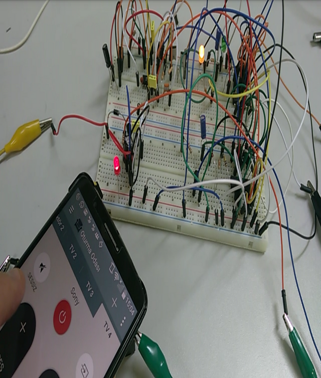
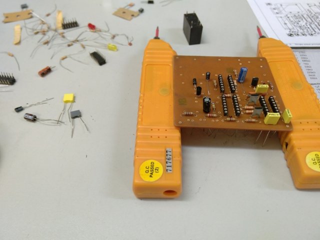
Before electronic circuits are created, an electronic circuit is installed on a perforated board. Electronic paths are made with many cables. Its operation is observed. Even if there are many different errors, it will be easier to fix.
Here we are building our electronic circuit. We use our phone as a remote. You need to download the remote control program to the phone. We see that the on-off commands are working on the phone. The red, yellow and green lights here are on with the command we give. Our feasibility study is completed.
We prepare our smoothly working electronic circuit in the drawing program (ISIS&ARES). In this program, all electronic equipment is connected to each other. This program has a simulation feature in it. Thanks to this feature, you can check if there are any errors in the program you redrawn.
Many electronic materials are needed for the lamp control circuit with the remote control. We can find these materials in the library in the program. Then we connect the electronic materials to each other.

Electronic card Making
After the operations, we need to draw electronic paths on the copper plate. After drawing these paths in a computer program, we need to print them out on a special paper. Then this paper is glued on a copper plate and ironed. With the ironing process, the lines on the paper pass onto the copper plate. Here you should put a cloth on it while ironing. If the cloth is not put in, the copper plate may burn.
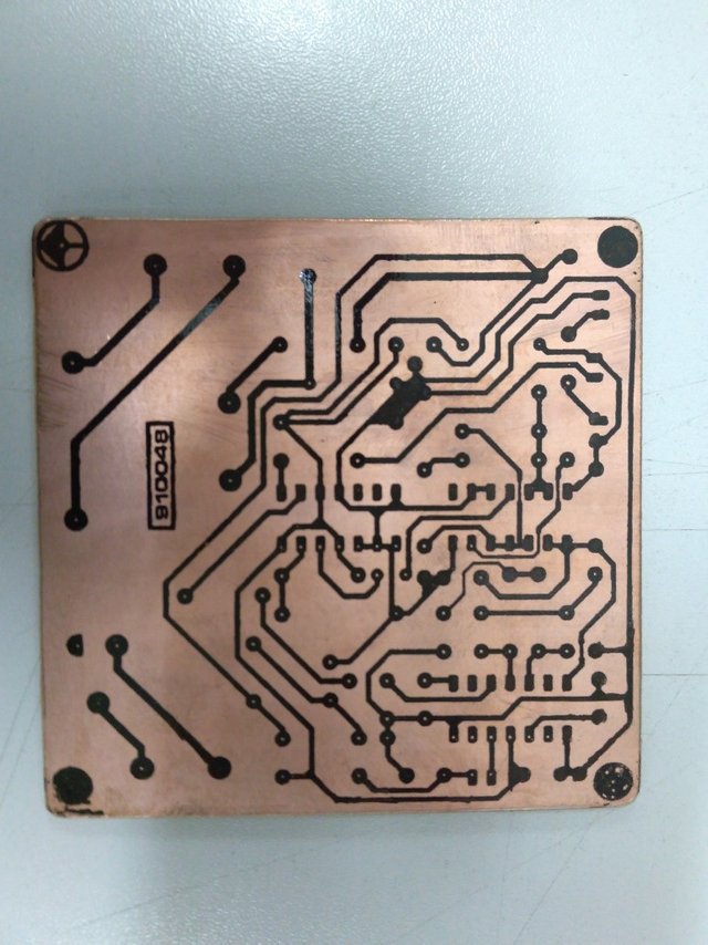
Black electronic paths formed on the copper plate. These lines will be our electronic paths. But the copper where there are no lines needs to melt and disappear. A special acid is required for this. When this card is thrown into acid, everything melts except the black lines.
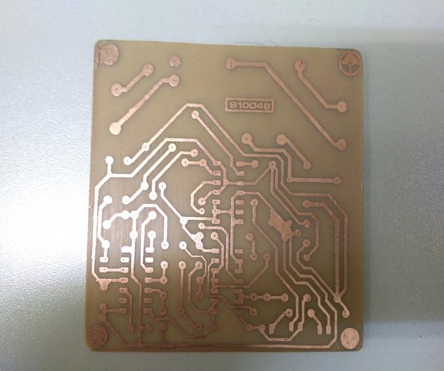
Then the card is removed from the acid. After drying, the black roads are cleaned with sandpaper. The roads in the photo below remain. It becomes our electronic card.
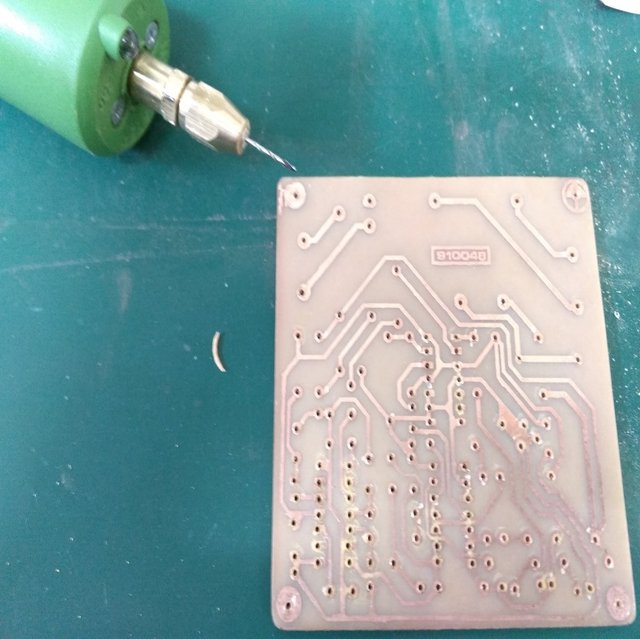
Electronic materials need to be placed on this Electronic card. Therefore, holes are drilled on the roads with an electric hand drill. Thanks to these holes, electronic materials can be placed on this card.
You have to be careful while drilling. Because if the copper where you drill the hole is erased, you cannot fix the electronic material there. That's why you should use a fine-tipped drill.
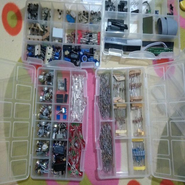
As I am an electronics and communication engineer, I love making this type of electronic circuits. That's why I have a lot of little electronic stuff in my bag.
There are many different electronic materials depending on the circuit you will make. You can see them in boxes. Resistor, capacitor, led, integrated and many other electronic materials.
We need to place electronic materials on the electronic card we have made. For this, you need to turn the card over. It is necessary to keep the card in the air by placing a support on its right and left sides. We insert electronic materials into the holes we drilled.
Each material has its own place. If you put it in different places, your electronic circuit will not work. Therefore, you should perform the assembly process slowly and accurately.
After the assembly process is completed, these materials are welded to the electronic board with solder and soldering iron. This serves to fix electronic materials.
As you can see in the photo, an electronic card comes out in this way. You should connect to the lamp with the green connectors you see on the left. After the connections are complete, all you have to do is turn on the lamp by pressing the button with the remote control.
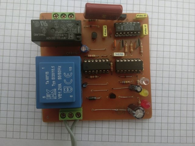
Let me briefly talk about how the lamp is lit. Infrared light comes out of the controller and is transferred to the receiver on this card. When the receiver on this board receives this signal, it triggers a relay. Energy is transferred when the relay is triggered. With this energy transfer, the light turns on in the lamp.
I hope it was a useful sharing for you. Your comments and support are important to me. Thanks for visiting my post. See you in the next post.
Stay Healthy. Goodbye.

This is so great....I graduated from the department of Electrical and Electronics Engineering 5years ago and i can remember vividly when i spent those years learning and practicing how to design electronics circuits.
I made a lot of circuits back then like Electronics message display, an Intruder detector systerm , sine wave inverters and a lot more, it was fun.
I used the breadboard for my test work.
And Preotus 8 for simulation after designing, i was so familiar with the interface and i am still familiar with it till now😊.
I wrote a lot of codes for my PIC, unfortunately, two years ago, i was robbed by armed robbers and i lost my laptop which contains all my source codes and that was how i lost over 400 different codes i wrote some years back😢. But i'm glad, i didnt lose the knowladge, i can always write it again whenever i get a new PC and i can always design any circuit depending on the function.
By the way, thank you for bringing back these memories, electronics is part of my life. So whenever i see it, i can't keep mute, it always spark that motivation in me.
Maybe i could actually learn some advance techniques from.
Dude, I'm glad we talked to you about the same issue here. Because here I met someone from my profession for the first time.
Good thing nothing happened to you during the armed robbery. You must be careful. Health is more important than anything else.
I made a post about Arduino before. Actually, it is not very difficult, I have no doubt that you will learn it easily. 👍
https://steemit.com/hive-181430/@whyshy/club100-tech-diary-game-or-11-03-22-or-timer-and-temperature-stabilizer-arduino-uno
Thanks mate for your comment. 😊
Its a pleasure meeting you Engineer, it is also my first time meeting someone in my field too over here. I'm so glad, and i hope to learn more.
I have checked the arduino article you sent, its much more clearer than i thought 😊, it's so interesting and i hope to read more of this from you, perhaps i could try out some of those real life projects.
Please which simulator do you use to carried some test, or do you do everything on Bread bored?
your work is very good, your friend is extraordinary, you can do it yourself, it's very important and always try to be grateful.
🥰
#club100
Absolutely I agree. Thanks for your comment. #club100 😊
Great jop my friend @whyshy #club100
🤗
Please, do not tag curator Sc01 in your posts. Thanks!
Hello, I will heed your warning. But I want to know who made the warning.
For a long time, Sc01 himself asked users not to mention it. Since then, we as administrators, Moderators or curators must correct this event.
@daytona475
Thanks @daytona475 . Actually, I know that tagging will not be done. That's why I didn't make this post in any community.
In addition, many authors with high reputation scores add sc01. Nobody wakes them up and I don't like it.
Thanks for the information again. have a nice day.