How a dirt cheap 433 MHz radio transmitter for Arduino works
I picked up a 433 MHz radio transmitter/receiver pair for less than a dollar awhile back and have finally gotten around to using them. I'm planning on using them to make remote temperature beacons that transmit the local temperature off to my receiver. But, in the meanwhile I wanted to write about this neat little transmitter.

The receiver/transmitter bundle costs about $0.70 USD (that's around 0.3 Steem right now) with free shipping on Ebay, although if you want to wait less than a few months you'll have to pay a hefty premium of a few extra dollars. The pair can be used to transmit sensor data (or anything else) between DIY electronics with a pretty low range (apparently a couple hundred meters) and a low data transfer rate. In terms of wireless information transmission, these are really the bottom of the barrel.
There's nothing to tear down since the modules come already exposed, but I've gone through and drawn up a schematic so that I can explain somewhat how they work.
Note that this post is just on the transmitter - I may cover the receiver at a future date, or I'll just include it in the temperature beacon project when it's done (read, after my classes for this quarter end ...)
Amplitude Shift Keying - ASK
One of the absolute simplest ways to transmitting data is called Amplitude Shift Keying.
You probably know that digital electronic signals involve only two values: "On" or "Off" (Low or High). "On" just means that whatever output pin the signal is coming out of has a high, nonzero voltage. "Off" just means that there is zero voltage on the pin relative to ground.
Amplitude shift keying lets us send digital signals wirelessly. Since any other number can be represented by a bunch of 1's and 0's via binary code, being able to send digital signals lets us send whatever information we want.
ASK is quite literally just turning the radio transmitter on and off. When a digital "On" reading comes in, the transmitter turns on. When an "Off" reading comes in, the transmitter turns off, or reduces in power. The result is that electromagnetic radio waves are transmitted in pulses.
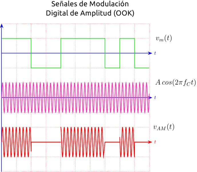
The bottom graph indicates an ASK transmission. Wave pulses are read as "On" and no pulse is read as "Off".
Credit
The radio receiver, separated by some distance, can then receive these signal pulses and re-produce the digital signal. Once you have the original signal, you can decode it to get back whatever message the transmitter was trying to send, all without wires or connections between the two devices. Behind the acronym and perhaps complicated plot, all ASK is is a radio transmitter turning itself on and off.
ASK isn't amazing for data transmission and as such isn't used that much for more advanced applications. But it's one of the simplest (and cheapest) ways to send non-audio data over the radio, so it comes into play for these stupidly cheap transmitter modules.
The Transmitter
The device doesn't have too many components, so I was able to draw up a full schematic. I utilized this page as a reference due to the weirdness of the PCB traces, but as my transmitter is significantly different I still had to do most of it myself.

The first thing to notice the "Data" line at the bottom of the schematic. This input comes in either "High" (+5 volts) or "Low" (0 volts). It is fed through a resistor into the base of a bipolar junction transistor (the S8050). Notice that this transistor connects the rest of the circuit to ground, so the top part of the circuit can't turn on until this transistor is opened. You can "open" these kind of transistors by pushing a current from the base (labelled B) to the emitter (labelled E). So, when the data input is "High" (+5 volts), a current flows from the data line to ground through the base of the S8050 transistor. This, in turns, "opens" the path between the Collector and Emitter and allows a current to flow through, "turning on" the top part of the circuit.
This data input is then the ASK part of the transmitter. When a 1 comes in from the data input, the transmitter is on. When a 0 comes in, the transmitter is off. So, the actualy transmitter (everything above the lower transistor) is simply creating a continuous radio wave.
For reference, here's the back of the device:

See the rectangular pads with solder on them? Those were supposed to be capacitors but the manufacturer cheaped out. See the schematic in the link I attached above for what these devices are supposed to look like.
The rest of the circuit is basically just a 433 MHz oscillator - that is, it creates a single that oscillates up and down 433 million times every second. The radio waves themselves are sent out of the antenna, which is a 17 centimeter long wire I soldered to the antenna pad. Since any EM wave travels at the speed of light in a vacuum, we can calculate the approximate wavelength of the wave from the frequency and add a quarter-wavelength antenna accordingly.
But 433 MHz is a pretty high frequency. It's not that easy to make a circuit oscillate this quickly (that's four times the frequency of normal FM radio, and ~400 times the frequency of AM transmissions). The second transistor is a specially made RF transistor that can easily oscillate at this frequency, but we still need something to drive the oscillations. The answer is something called a SAW resonator:

433.92 MHz SAW resonator onboard the transmitter
SAW resonators act kind of like crystal resonators, which are found in things like clocks. Crystal resonators oscillate at a very specific resonant frequency, allowing a circuit to be tuned to a precise timing. You can use one to make a circuit operate precisely at the chosen frequency, which is useful if you need to transmit on just one frequency. They are also found in digital clocks and can be used to set the processing frequency for microcontroller chips.
But SAW (surface acoustic wave) resonators usually have way higher frequencies than crystal oscillators. This one have a resonant frequency of 433.92 MHz. As such, the transmitter send out 433.92 MHz radio waves (actually I suppose they are microwaves at this point).
The combination of the SAW resonator and the high frequency transistor lets the circuit oscillate at, you guessed it, 433.92 MHz. I assume the inductors are for filtering the input signal and removing noise. The single capacitor is just for connecting the antenna.
Conclusion
The result is a super cheap little transmitter that can be used to send your favorite information across the air. Like I said, when I get a little less busy I'd like to use one of these to make a little temperature transmitter.
What's really funny is that I've looked at those SAW resonators, and they cost about $1.50 a pop in low quantities. The manufacturer of the transmitter is probably buying them in bulk, but that means it's cheaper to buy these devices and take off the SAW resonator if you need it than to just buy the resonator outright. And if you do that, you get free ASK radio receivers.
Let me know if you have any questions, or any corrections.
Thanks for reading!
All images not credited are my own. You are welcome to use them with credit.
Sources/Datasheets:
R433 SAW Device Datasheet
2SC3356 RF Transistor Datasheet
Being A SteemStem Member
What kind of bitrate could you get with this setup? 433.92 MHz isn't exactly WIFI (but not AM radio either).
Appears to be just under 5 kilobits per second, so pretty low. You won't be able to send pictures with this but sending short strings with sensor data is totally doable.
Thanks for the reply!
I used 433MHz TC3 modules with an Arduino to send control signals to 20 different LED strips. Bitrates are low, but still pretty impressive what can be done with these things. And, a good choice since many RF based remote controllers use 433 so you can do rather a lot with this setup.
I did find that our paricular devices expected a preamble series of bits sent and commands needed to be sent multiple times. This wasn't documented :)
If you'll permit a link: http://ivx.org.nz/portfolio/tree-of-light/
To listen to the audio version of this article click on the play image.

Brought to you by @tts. If you find it useful please consider upvote this reply.
Awesome electronics write-up, as usual. Thanks for taking the time to walk us through the parts. I always loved taking things apart from a very young age, but really could have used the help of someone to identify parts and explain their functions.
Sounds pretty much technical thanks for sharing.
This is lovely, it reminds me of old times..... Nice work
pretty cool but i think we all know almost no1 here is gunna do that shit.
Boost Your Post. Send 0.100 STEEM or SBD and your post url on memo and we will resteem your post on 5000+ followers. check our account to see the follower count.
Spamming to get 20 cents? Do I smell a hijacked account?
could be a alien ai man maybe we are alien robots cum in my asshole u robot bitches!