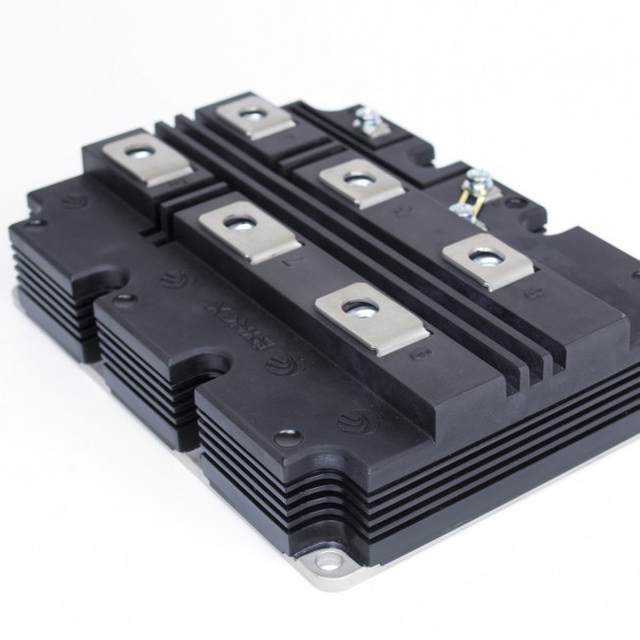
Characteristics And Applications Of Semiconductor Power Devices : Power MOSFET And IGBT Transistors
Technologies in the field of power electronics are constantly being improved: relays become solid-state, bipolar transistors and thyristors are being replaced more and more by field-effect transistors, new materials are being developed and used in capacitors, etc. - an active technological evolution that is not stopped for a year . With what is it connected?
This is obviously due to the fact that at some point the manufacturers are not able to satisfy consumers' requests for the capabilities and quality of power electronic equipment: the relay sparks and burns contacts, bipolar transistors for control require too much power, the power blocks occupy unacceptably a lot of space, etc. Manufacturers compete among themselves - who will be the first to offer a better alternative ...?
This is how the field MOSFET transistors appeared, thanks to which the flow control of the charge carriers became possible not by changing the base current, as in the bipolar ancestors, but by the electric field of the gate, in fact - simply applied to the gate voltage.
 |  |
|---|
As a result, by the early 2000s the share of power devices on MOSFET and IGBT was about 30%, while bipolar transistors in power electronics remained less than 20%. In the last 15 years, an even more significant leap took place, and bipolar transistors in the classical sense almost completely gave way to MOSFET and IGBT in the segment of controlled power semiconductor switches.
Designing, for example, a power high-frequency converter, the developer already chooses between MOSFET and IGBT - both of which are controlled by the voltage applied to the gate, and not at all by current, like bipolar transistors, and the control circuits result in simpler ones. Let us, however, consider the features of these very transistors, controlled by the gate voltage.
MOSFET or IGBT
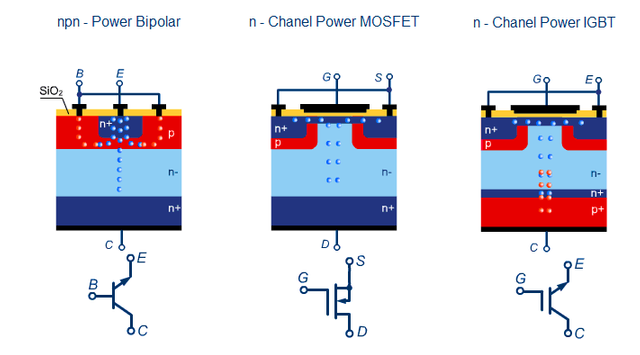
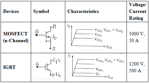
In IGBT (an IGBT bipolar transistor with an isolated gate) in the open state, the operating current passes through the p-n junction, while in the MOSFET - through the drain-source channel, which has a resistive character. The power dissipation possibilities for these devices differ, the losses are different: in the MOSFET-field, the power dissipation will be proportional to the square of the current through the channel and the channel resistance, while at the IGBT the dissipated power will be proportional to the collector-emitter saturation voltage and current through the channel in the first degree.
If we need to reduce the losses on the key, then we need to choose a MOSFET with a lower channel resistance, but do not forget that with increasing semiconductor temperature this resistance will increase and the heat losses will still increase. But with IGBT, as the temperature rises, the saturation voltage of the p-n junction decreases, on the contrary, it means that the losses for heating decrease.
But not everything is as simple as it may seem at the sight of an inexperienced person in power electronics. The mechanisms for determining the losses for IGBT and MOSFET are radically different.
As you understand, with a MOSFET transistor, the resistance of the channel in the conducting state causes certain power losses on it, which according to statistics are almost 4 times higher than the power used to control the shutter.
In IGBT, the situation is exactly the opposite: there are fewer losses at the transition, but more energy is spent on management. Speech about frequencies of about 60 kHz, and the higher the frequency - the greater the loss of gate control, especially with respect to IGBT.
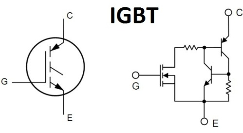
The thing is that in the MOSFET, the minority charge carriers do not recombine, as in the IGBT, which includes a field MOSFET transistor that determines the speed of the opening, but where the base is not available directly, and it is impossible to speed up the process using external circuits. As a result, the dynamic characteristics of the IGBT are limited, and the limiting operating frequency is also limited.
Increasing the transmission ratio and reducing the saturation voltage - say, we will reduce the static losses, but we will increase the losses when switching. For this reason, manufacturers of IGBT-transistors indicate in the documentation for their devices the optimum frequency and maximum switching speed.
There is a drawback in MOSFET. Its internal diode is characterized by a finite time of reverse recovery, which somehow exceeds the recovery time, which is characteristic for internal antiparallel IGBT diodes. As a result, we have switching losses and current overloads in MOSFET in half-bridge circuits.
Now directly about the heat dissipated. The area of the semiconductor IGBT structure is larger than that of the MOSFET, so the dissipated power of the IGBT is larger, but the transition temperature during the key operation increases more intensively, so it is important to correctly select the radiator to the key, correctly calculating the heat flux, taking into account the thermal resistances of all boundaries assembly.
MOSFET at high power also has heating losses, greatly exceeding the losses for IGBT shutter control. At capacities above 300-500 W and at frequencies in the region of 20-30 kHz, the advantage will be behind the IGBT transistors.
In general, for each task they choose their own type of key, and there are certain typical views on this aspect. MOSFETs are suitable for operation at frequencies above 20 kHz with supply voltages up to 300 V - chargers, switching power supplies, compact small power inverters, etc. - the vast majority of them are assembled today on the MOSFET.
IGBTs work well at frequencies up to 20 kHz at voltages of 1000 and more volts - frequency converters, UPS, etc. - that's the low-frequency segment of power equipment for IGBT transistors.
In the intermediate niche - from 300 to 1000 volts, at frequencies of the order of 10 kHz, - the selection of the semiconductor key of a suitable technology is carried out exclusively individually, weighing the pros and cons, including price, dimensions, efficiency and other factors.
Meanwhile, one can not say unambiguously that in one typical situation it will be IGBT, and in the other - only MOSFET. It is necessary to approach the development of each specific device in a complex manner. Based on the power of the device, its operating mode, the expected thermal conditions, acceptable dimensions, control features of the circuit, etc.
And most importantly - selecting the keys of the right type, it is important for the developer to accurately determine their parameters, because in the technical documentation (in datashit) it does not always exactly correspond to reality. The more accurately the parameters are known, the more effective and reliable the product will be, regardless of whether it is an IGBT or MOSFET.
Bipolar and field effect transistors - what is the difference
Current or field
Most people, one way or another interfering with electronics, the basic arrangement of field and bipolar transistors should be known. At least from the name "field-effect transistor", it is obvious that it is controlled by the field, the electric field of the shutter, while the bipolar transistor is controlled by the base current.
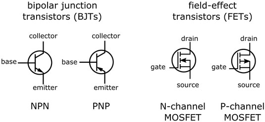
Current and field - the difference here is cardinal. In bipolar transistors, the collector current is controlled by changing the control current of the base, while to control the drain current of the field-effect transistor, it is sufficient to change the voltage applied between the gate and source, and no control current is needed as such.
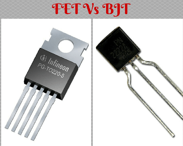
FETs faster
Which transistors are better than field or bipolar transistors? The advantage of field-effect transistors, in comparison with bipolar ones, is obvious: field-effect transistors have a high input resistance in direct current, and even control at high frequency does not result in significant energy costs.
Accumulation and resorption of minority charge carriers is absent in the field effect transistors, hence the speed at which they are very high (as noted by the developers of power equipment). And since the transfer in the field effect transistors corresponds to the portable main charge carriers, the upper bound of the effective amplification of the field-effect transistors is higher than that of the bipolar ones.
Here we note the high temperature stability, the low level of interference (due to the lack of injection of minority charge carriers, as it happens in bipolar carriers), the economy in terms of energy consumption.
Different reaction to heating
If the bipolar transistor is heated during operation of the device, then the collector-emitter current increases, that is, the temperature coefficient of resistance of bipolar transistors is negative.
In the field, the opposite is true: the drain-source temperature coefficient is positive, that is, as the temperature rises, the resistance of the channel also increases, that is, the drain-source current decreases. This circumstance gives the field-effect transistor another advantage over bipolar ones: field-effect transistors can be connected in parallel without fear, and no equalizing resistors are needed in the circuits of their drains, because according to the increase in the load, the resistance of the channels will automatically grow.
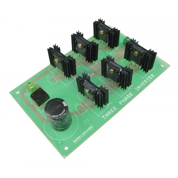
So to achieve high switching currents, it is easy to type a composite key from several parallel FETs, which is used a lot in practice, for example in inverters (see - Why modern transistors and not tiasters are used in modern inverters).
But bipolar transistors can not just be paralleled, they need necessarily current-equalizing resistors in emitter circuits. Otherwise, due to imbalance in a powerful composite key, one of the bipolar transistors will sooner or later have an irreversible thermal breakdown. The field compound keys are almost non-threatening. These characteristic thermal features are associated with the properties of a simple n- and p-channel and p-n junction, which are radically different.
Areas of application of those and other transistors
The differences between field and bipolar transistors clearly distinguish between their applications. For example, in digital microcircuits, where a minimum current consumption in the standby state is required, the field effect transistors are used today much more widely. In analogue microcircuits, FETs help achieve high linearity of the gain characteristic in a wide range of supply voltages and output parameters.
Schemes such as reel-to-reel are conveniently implemented today with FETs, because it is easy to achieve a range of output voltages as signals for the inputs, coinciding with almost the voltage level of the circuit. Such circuits can simply connect the output of one to the input of the other, and do not need any voltage limiters or dividers on the resistors.
As for bipolar transistors, their typical applications remain: amplifiers, their cascades, modulators, detectors, logic inverters and chips on transistor logic.
Fields win
Outstanding examples of devices built on FETs are a wrist watch and a remote control for a TV set. Due to the use of CMOS-structures, these devices can work up to several years from one miniature power source - a battery or a battery, because they practically do not consume energy.
Currently, field-effect transistors are increasingly used in various radio devices, where they are already successfully replacing bipolar ones. Their use in radio transmitting devices allows to increase the frequency of the carrier signal, providing such devices with high noise immunity.
Possessing low resistance in the open state, they find application in the final cascades of high-power audio power amplifiers (Hi-Fi), where again bipolar transistors and even electronic lamps are successfully replaced.
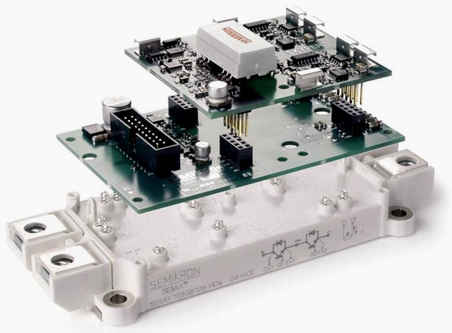
In high power devices, such as soft starters for motors, IGBTs, devices that combine both bipolar and field effect transistors, already successfully replace thyristors.
References for Text and Images:
- http://www.datasheetarchive.com/files/motorola/design-n/ppd/html/psvol2-1/art01.htm
- https://gradeup.co/characteristics-of-semiconductor-power-devices-i-7aa518ad-c025-11e5-9728-5704373972d9
- http://www.efxkits.us/difference-between-insulated-gate-bipolar-transistor-igbt-and-mosfet/
- https://electronics.stackexchange.com/questions/219323/what-is-the-difference-between-driving-a-mosfet-gate-and-an-igbt-gate
- https://www.electronicspecifier.com/power/meet-the-transient-power-challenge
- http://micro.rohm.com/en/techweb/knowledge/si/s-si/03-s-si/5612
- http://www.rfwireless-world.com/Terminology/MOSFET-vs-IGBT.html
- http://www.snmreddy.com/2016/03/the-mosfet-metal-oxide-fet.html
- http://www.powerguru.org/driver-circuits/
Support @steemstem and the #steemstem
project - curating and supporting quality STEM
related content on Steemit

This post has received a 0.28 % upvote from @booster thanks to: @biomanu.
This post has received a 0.72% upvote from thanks to: @biomanu.
For more information, click here!!!!
Send minimum 0.100 SBD to bid for votes.
Do you know, you can also earn daily passive income simply by delegating your Steem Power to @minnowhelper by clicking following links: 10SP, 100SP, 500SP, 1000SP or Another amount. (10 SP minimum)
Greetings! I am a minnow exclusive bot that gives a 5X upvote!
I recommend this amazing guide on how to be a steemit rockstar!
I was made by @EarthNation to make Steemit easier and more rewarding for minnows.