Electrical Component Basics: Piezoelectric Resonators
I've finally got another technical post today. My schedule got extremely busy in the last week but it's finally getting better with finals being this week (my courseload was such that the week before finals was far worse than the actual finals, by orders of magnitude). Now that I've gotten around to writing, I'd like to discuss Resonators, a type of simple electrical component.
At the core of many clocks, processors, radios, and cell phones are little devices know as resonators. These components resonate at a very precise, specific frequency. This lets a device generate a precisely timed signal that can be used to accomplish many tasks, not the least of which is accurately tracking the passage of time. I've brought up resonators a lot in my posts so I decided it was about time I actually did a post dedicated to them.
Resonator Basics
A resonator is really just a way to set the frequency of an electrical signal. For example, a 16 MHz resonator can be used to generate a sine wave at almost exactly 16 MHz. If you need to generate a 16 MHz radio wave, you can make one that is almost exactly on the mark (frequency wise) using a resonator.

Various crystal oscillators
Credit
That's why you find resonators in essentially every digital clock. The resonator provides precise timing by generating a signal at a certain frequency that is always exactly on time. This signal, oscillating at an exact frequency, can then be used to determine how much time has passed since the device was turned on.
There are many other resonators other than the types I'm discussing here (the simplest of which is a coil of wire connected to a capacitor). However, when you find a single part in a circuit that acts as a resonator and is tuned to a certain frequency, it will probably be a piezoelectric resonator.
Piezoelectricity
Certain materials are called piezoelectric if they react mechanically to electric field. Quartz is a common piezoelectric material. If you apply a voltage across a piezoelectric material (say with a battery) you will produce a stress in the material, and it will bend. This of course also works in reverse: Bend a piezoelectric material and it will generate a voltage that can turn on circuits or charge things.
Piezoelectric materials are used for a ton of applications, including the buzzer in your microwave (this involves an alternating current being applied to a thin piezoelectric membrane that vibrates with the signal, generating a sound wave).
The important thing to notice is that piezoelectric materials react mechanically to electric fields, and react electrically to mechanical stress.
Types of Resonators
I'll be covering three major types of piezoelectric resonators: Ceramic, Crystal, and SAW.
Ceramic Resonators
As the name suggests, ceramic resonator contain a piezoelectric, ceramic material that will vibrate (mechanically) at a very specific frequency when electric signals are applied. Ceramic resonators are extremely inexpensive - Digikey right now is showing me that 4 MHz ceramic resonators can be had for $0.20 a piece in bulk. Although they will oscillate at a specific frequency, it isn't amazingly accurate - usually within a percent of the labelled frequency.

16 MHz Ceramic Resonator Device
Credit
This means that ceramic resonators can be used when cost is more important than accuracy. If a circuit doesn't need to have an amazingly perfect timing frequency but the manufacturer would like to save some money, ceramic resonators can be used.
These devices usually look like some sort of odd capacitor, and will have the frequency labelled on the outside.
Crystal Oscillators
The more common type of resonance device is the crystal oscillator. These devices contain a crystal (often quartz) that will vibrate at an extremely precise frequency, down to fractions of a percent off from the labelled frequency.
Because they are so precise, crystal resonators are used in most complex circuits: To name a few, cell phones, computers, radio receivers and transmitters, microcontroller boards (like Arduino), watches, and Bluetooth and WiFi devices will all have crystal oscillators onboard.

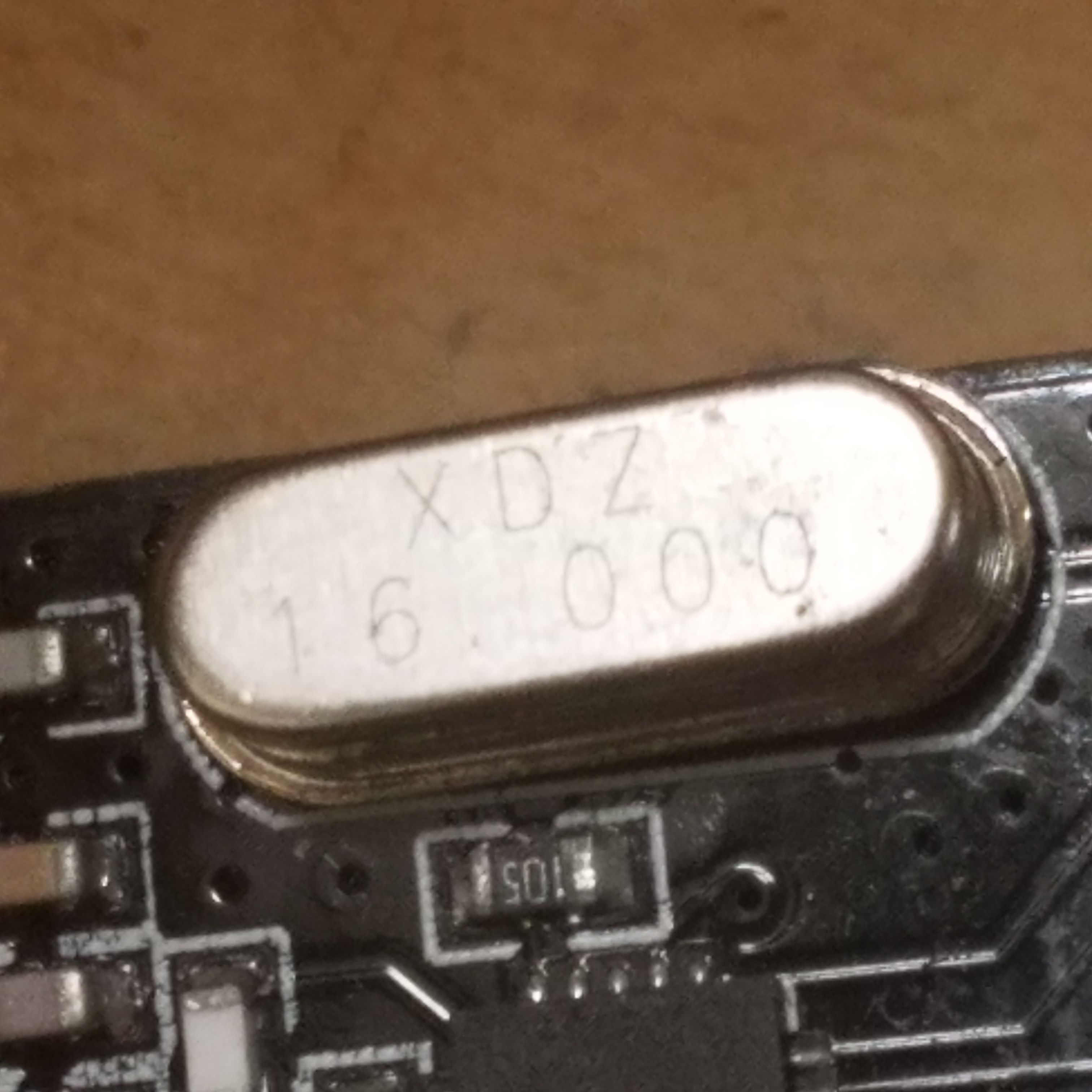
A 16.000 MHz crystal oscillator on a 2.4 GHz transmitter module. Notice the decimal places indicating that the device is accurate down to three zeros.
Crystal resonators can resonate at frequencies reaching into the megahertz range. They look like little metal boxes or canisters on circuit boards, and will usually either look like the rounded rectangle above, or a long metal canister that look somewhat like a capacitor. They cost more than ceramic resonators, but make up for it with their incredibly precise timing.
SAW Resonators
SAW (Surface-Acoustic-Wave) resonators are devices that can work like crystal oscillators up into much higher frequency ranges. SAW resonators usually cost more than the other two types but can be made to oscillate at much higher microwave frequencies.
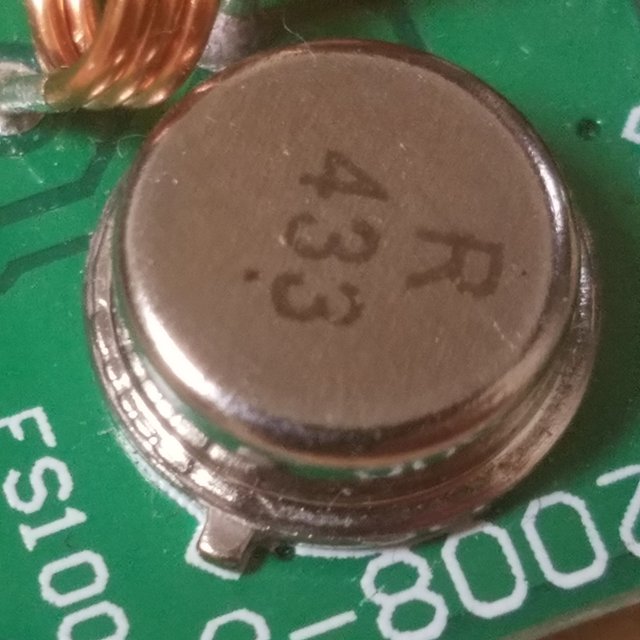
For example, I own a cheap 433 MHz radio transmitter (see here for a writeup) that uses a 433.92 MHz SAW resonator to generate this ultra high frequency (yes this is the actual term for frequencies between 300 and 3000 MHz) radio wave that can send sensor data to a receiver. The resonator means that the only semiconductor device needed for the actual transmitter portion is a single RF transistor, and the overall device can be made with very few materials.

433.92 MHz SAW Oscillator Device
You can use a SAW device to generate a precise signal or radio wave at frequencies far higher than any signal generated by a crystal or ceramic resonator. This makes them useful for radio transmitters with one channel, which is really what the device I just mentioned is.
Electrical Model of a Crystal Oscillator
A crystal resonator actually acts like a simple circuit, consisting of two capacitors and an inductor:

Crystal resonator equivalent circuit
Credit
L is usually really big, C1 is usually very very small, and C0 is usually small but larger than C1.
Inductors generate voltages when the current through them changes. Capacitors generate currents when the voltage across them is changed. The result is that, together, they form resonant circuits that also oscillate at a precise frequency.
In the case of a crystal, we have a series LC circuit (L and C1) and a parallel LC circuit (L, C1, and C0). Each of these circuits will have its own resonant frequency. In practice, the series and parallel frequencies are almost identical, resulting in what we see as a single resonant frequency for a crystal.
I don't know about you, but when I saw this for the first time I was really confused as to how, physically, the above circuit could work. To help you understand I've used Falstad, a simple online circuit simulator, to build a simple crystal oscillator circuit. To see for yourself, you can visit the following link (http://www.falstad.com/circuit/) and load in the following circuit by importing this text:
$ 1 0.0000049999999999999996 0.22070718156067046 54 5 43
v 144 272 144 176 0 0 40 5 0 0 0.5
r 288 176 288 256 0 27000
c 288 256 528 256 0 0.00001 -4.735623993184948
w 528 176 528 256 0
w 288 256 288 304 0
l 384 304 528 304 0 1 -0.01760900944907503
w 528 256 528 304 0
t 288 304 224 304 0 1 -4.735623993184948 0.26437600681505213 100
w 224 176 224 288 0
w 144 176 224 176 0
w 224 176 288 176 0
w 288 176 528 176 0
w 144 272 144 320 0
w 144 320 224 320 0
c 288 304 384 304 0 0.00001 -3.2554113973507994
o 8 64 0 4099 5 1638.4 0 2 8 3
Fiddle with the current and simulation speed dials until you can clearly see what is happening. The two capacitors and inductor form a resonant circuit that produces a seesaw of current. When the seesaw pushes one way, the transistor gets opened by current flowing through the base and lots of current flows through the transistor. When the seesaw goes back the other way, the transistor closes (the base of a transistor acts like a diode - current only flows one way) until the current reverses again.
The result is an oscillation precisely determined by the values of L, C1, and C0. I made these values reasonable numbers, but for a crystal, these values would be much different to produce much higher, precise frequencies. Note that the circuit above produces an oscillation that eventually dies out due to the capacitors charging up. Turning off the circuit and turning it back on will restart the cycle.
Conclusion
In short, the properties of special piezoelectric materials can be exploited to generate really accurately timed electrical signals. The computer you are reading this on relies on these devices to operate.
Let me know if you have any questions, comments, or corrections. I don't expect to be able to write at my previous daily schedule for a little bit longer but I do hope to be more active in the coming weeks.
Thanks for reading!
All images not credited are my own. You are welcome to use them with credit.
References:
Quartz Crystals - Radio Electronics
Ceramic Resonator Wikipedia Entry
SAW Wikipedia Entry
Crystal Oscillator Wikipedia Entry
Farnell SAW Resonator Datasheet
Nifty oscillator explanation. I'm happy that you have included explanation of how piezoelectricity works. :)
Regardless, keep up the good work. Cheers!
Just a small notice from me: It is possible to use subscript by typing <sub>things to be subscript</sub> :
C0, C1
(it at least works in the preview - and sup is for superscript: 109 Hz)
good..
Nice!
Congratulations! This post has been upvoted by SteemMakers. We are a community based project that aims to support makers and DIYers on the blockchain in every way possible. Find out more about us on our website: www.steemmakers.com.
If you like our work, please consider upvoting this comment to support the growth of our community. Thank you.
Being A SteemStem Member