Learnwithsteem : Teaching robotics using the ESP32 board - Second lesson
Hello steemians,
In this second course, you will learn how to use the HC-SR04 ultrasonic sensor with our ESP32 programmable board to detect the distance to an object using MicroPython firmware. This article shows the steps of wiring the sensor to the ESP32 board by providing simple MicroPython code to get the distance to an object and display it on a screen.
What do we need to start?
Of course to be able to practice these steps, you must have the MicroPython firmware installed correctly in your ESP32 board, and to code the program you must have an IDE, for our case we will use Thonny (You can follow how to install the firmware and flash the board using this IDE in the first tutorial).
What is an HC-SR04 ultrasonic sensor?
Well, the HC-SR04 is a low-resolution ultrasonic distance sensor. With it, it allows you to easily and quickly measure distances, although in principle it is not usually used for this. It is often used as a transducer for obstacle detection and avoidance through other mechanisms associated with sensor response. The sensor reads distances from about 2 cm to 400 cm, with an error area not exceeding 0.3 cm, so it is used in most projects.
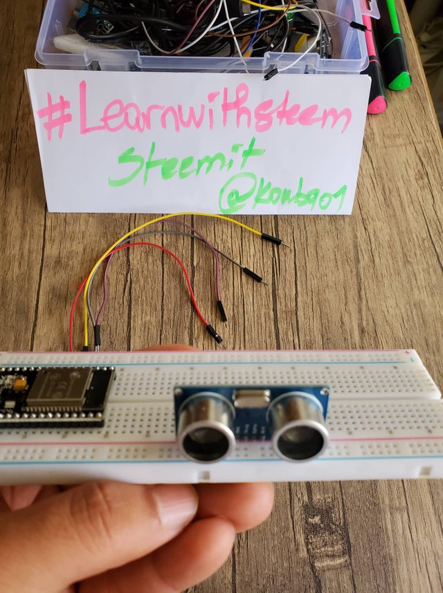
I'm going to show you both sides of this sensor to better see its components and pins.
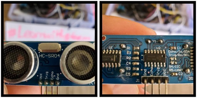
My own shoot
As you can see in the images, this sensor essentially has 4 pins that we will explain the meaning of each one in the table below:
| Pin | Signification |
|---|---|
| Pin1 (Vcc) | This pin provides +5V power to the sensor. |
| Pin2 (Trigger) | This is an input pin used to initialize the measurement by sending ultrasound by keeping this pin high for 10us. |
| Pin3 (Echo) | This is the output pin, which rises for a specified period of time and will be equivalent to the length of time it takes the wave to return to the sensor. |
| Pin4 (Ground) | This is the GND pin used to connect to the GND of the system. |
How does the HC-SR04 ultrasonic sensor work?
To calculate the distance to an element the sensor uses a sonar which works as follows:
- Its transmitter called trig pin sends a high frequency sound (40 kHz).
- This sound propagates in space, once it detects an element, it returns to the map.
- Its receiver called echo pin accepts reflected sound (echo).
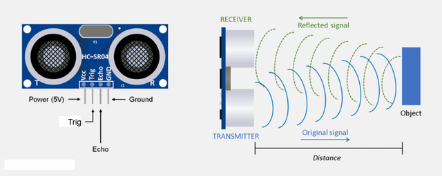
To make its calculation, the ESP32 card takes into account two main factors, namely the time elapsed between transmission and reception as well as the speed of sound in space to obtain the following formula: Distance = ((speed)*time)/2
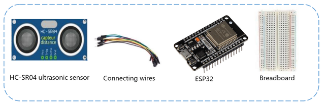
Equipment required:
To complete the assembly, you will need the following parts:
- The ESP32 card plugged into its board
- HC-SR04 ultrasonic sensor
- the connecting wires
How to perform the Mount on the board?
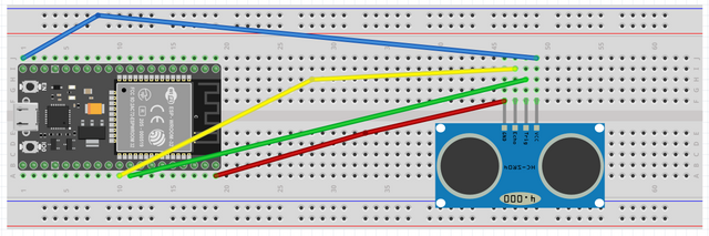
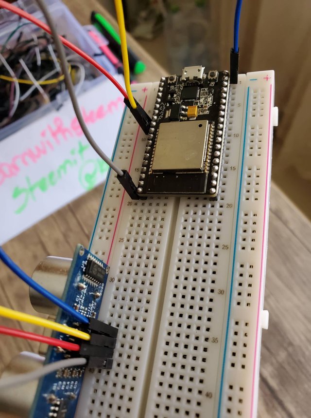
To carry out the assembly, we connect:
- The 5V supply from the ESP32 board goes to the VCC pin of the sensor.
- The GND pin of the ESP32 board goes to the GND pin of the sensor.
- Pin 5 of the ESP32 board goes to the TRIGGER pin of the sensor.
- Pin 18 of the ESP32 board goes to the ECHO pin of the sensor.
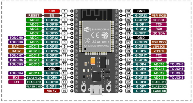
You can check the ESP32 pinout reference guide below.
Code the program:
- We must also upload the Library hcsr04.py (save it on the ESP32 board) downloaded from link next (right click on the link then save the link as)
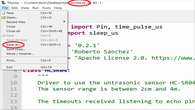
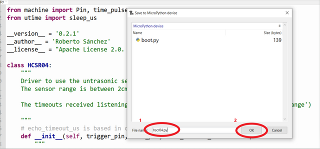
1- After downloading the hcsr04.py file, Open Thonny, Access the File menu and choose the Save As...
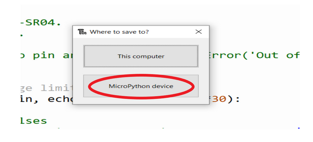
2- Choose save in “MicroPython Device”:
3- Give the name hcsr04.py to the file to save after pressing the OK button:
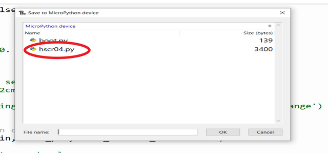
Now the file is well saved in the card and you can benefit from all its features.
Coding :
Context :
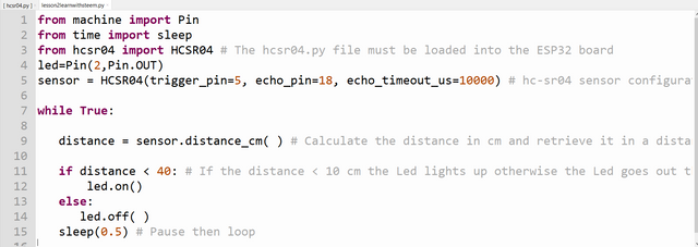
The purpose of this program is to turn on the integrated LED (Pin2) with a distance sensor.
If the sensor detects an obstacle < 10 cm: the LED lights up, otherwise the LED goes out.
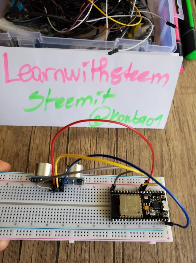
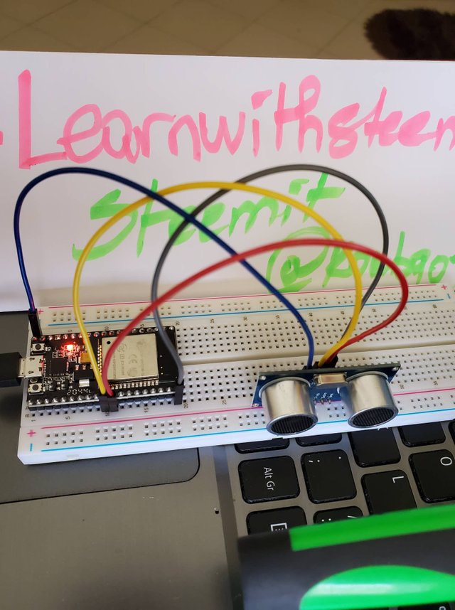
The realization of assembly and the execution in image:
- Prepare all the necessary equipment:
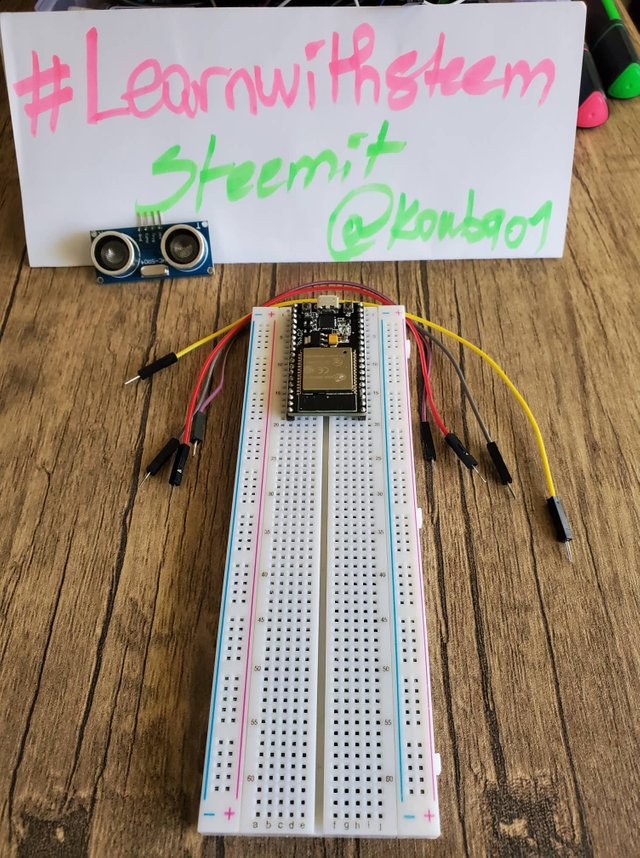
- Start by connecting the Hcsr04 sensor to the board and then use the wires to link its pins with the pins of ESP32.
Connect the ESP32 to the PC through its USB port, the internal red LED lights up to indicate the presence of current.
Save the program on ESP32 and run it.
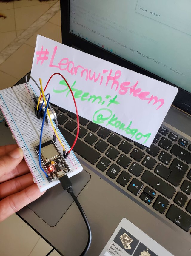
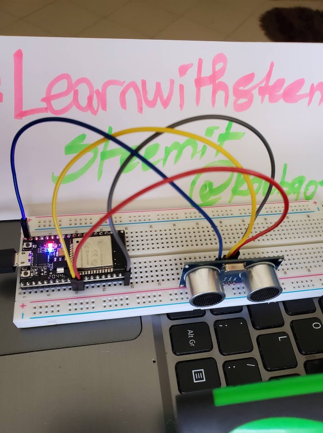
-You can test the code through an object (I used my green marker)
- We notice when the marker approaches at a distance <40cm the blue internal LED lights up otherwise it goes out.
Thank you for your follow and see you in the next part.

As an electronic communications engineer, I was happy to see these electronic projects on this platform.
Programming and implementing these circuits with Arduino or Esp32 board is actually quite simple.
With the article you wrote, many people can easily understand the basic logic of the business.
During my university years, I did quite different projects like these. All of them were very fun for me.
I am glad to find interested users of this domain, and I hope to continue to present other projects with higher levels.
Here are a few articles I've shared before.
Timer and temperature stabilizer. - Arduino UNO
Lamp control with remote control. 💡
Construction of a 4 propeller drone. 🚁
I will definitely be following. Thanks have a good day.
Great work @whyshy.
Thank you so much. @kouba01
Thank you for contributing to the #LearnWithSteem theme. This post has been upvoted by @maazmoid123 using the @steemcurator09 account. We encourage you to keep publishing quality and original content in the Steemit ecosystem to earn support for your content.
Regards,
Team #Sevengers
Thank you sevengers team for your curation.
Hello, @kouba01. Your article has been supported using the @steemcurator05 account.