Interpretation of Circuit Diagram/Circuit Building
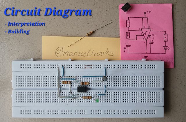 Captured and edited With Galaxy-A15
Circuit Interpretation and Building
In Electronics, a circuit diagram, which is also known as a schematic diagram, is a representation of an electronic circuit, a blueprint that is presented using garphical symbols, lines, and other visual elements to represent the components and connections in the circuit.
Components of a typical circuit diagram:
Name;
A good circuit diagram should have a name for the circuit. And a good name should be a descriptive name.
Lines;
The lines on an electronic circuit diagram represents wires or connections between the constituting components in the circuit.
Symbols;
Each component like resistor, transistor, capacitor etc is represented on a circuit, using a unique circuit symbol with markings that clearly indicate their orientation.
Values;
Numbers and units are attached to this symbols to specify their value.
Labels;
The labels on a circuit are used to identify components. An IC could be labeled as NE555P, a sub circuit or node or section could be labelled. Even the pins on an integrated circuit has Labels.
Graphical elements;
A circuit may have arrows pointing to the direction of flow, circles, or rectangles, to illustrate circuit behavior or functionality. It can also be used to show the wave form or type of current in that section of the circuitry.
Circuit Diagram Rationale
For Education
You will probably need a circuit diagram when teaching electronics concepts and circuit analysis. It helps simplify electronic concepts.
For Documentation
If you want to clearly communicate circuit information to someone or a group, you will definetly need a circuit diagram to communicate the complex ideas easily.
For Design
When creating and visualizing new circuit design, or making an upgread on the existing circuit, you will need a circuit diagram for that.
Troubleshooting
During troubleshooting, if you should come across a completely burnt component, you will need the circuit diagram for identification to aid replacement.
Manufacturing
You will also need a circuit diagram to guide the assembly and production of electronic devices.
Workshop 1
[Task 1]
Constructing a simple corcuit
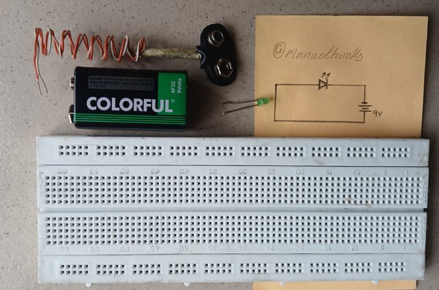
Component measuring/testing instruments:
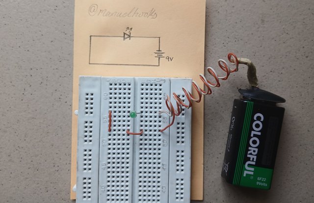
[Fig.1]
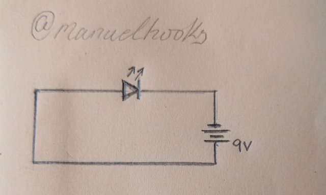 Fig.1 (Circuit Diagram)
| Components | Qty |
|---|---|
| LED | 1 |
| 9v Battery | 1 |
| Conectors | - |
Observation
Once the LED's polarity was corrected and the last connecting cable got fixed in, the LED shone bright-orange and gradually got burnt out and never light up again. The 9v battery was definetly too much for the LED.
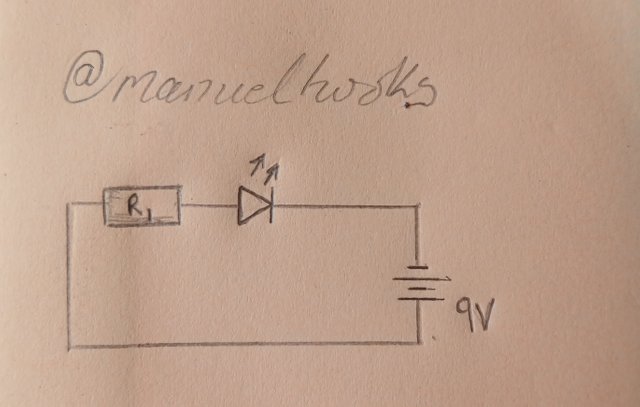
Fig. 2
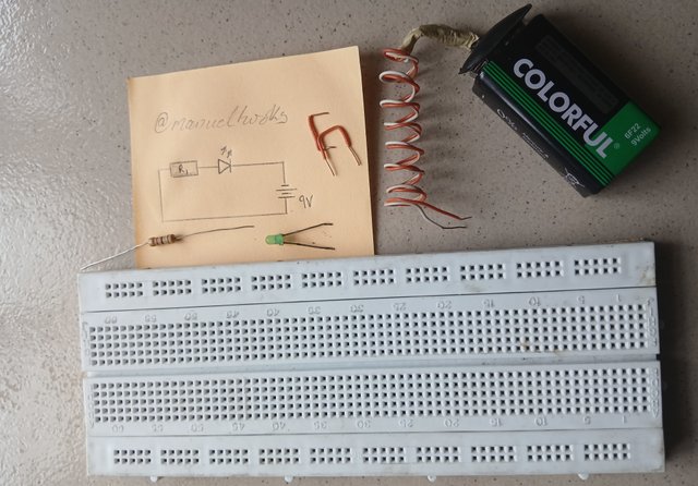
| Components | Qty | Rating |
|---|---|---|
| LED | 1 | - |
| Resistor | 1 | 1k |
| Battery | 1 | DC 9v |
| Conectors | - | - |
Fig.2 (Circuit components)
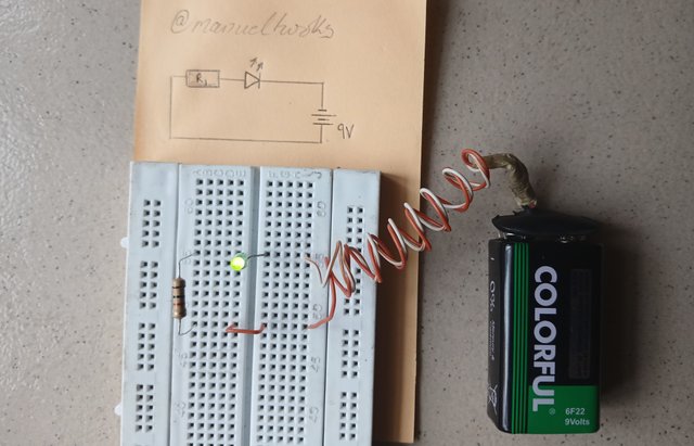
Fig.2 (Constructed Circuit)
Observation
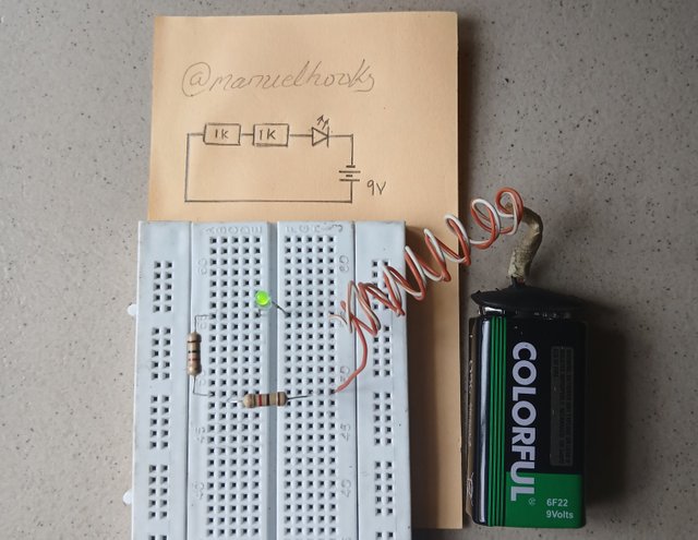
When the last connecting cable got fixed in, the LED came up green and has been on till i captured it and is still on. The 1000 ohms resistor is creating a favourable condition for the Light Emitting Diode to function properly. The 9 volt battery was too much for the LED and the resistor is preventing it from burning out.
[Task 2]
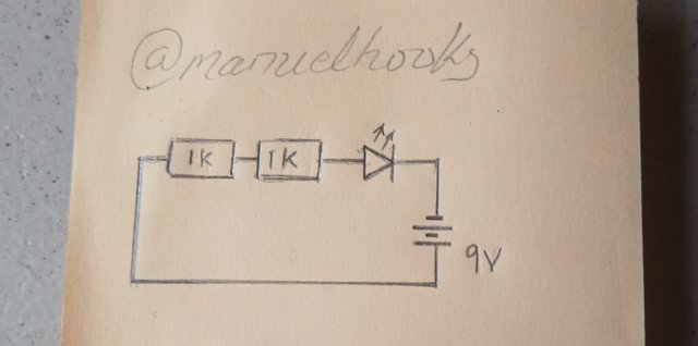
Draw a circuit diagram of an LED attached to 2 resistors of 1k ohms connected in series, powered with 9V battery source. What steps did you take in drawing this?
What steps did you take in drawing this?
Step 1: understand the question.
I am to draw a circuit.
Step 2: Identify the components involved.
This circuit had two resistors, 1k Ω each connected in series, an LED and a 9v battery.
Step 3: drawing.
Draw the resistors in series, followed by the LED, then the battery.
Observation
This circuit was able to light up the LED though the brightness was lower compared to the circuit in fig 2.
[Task 3]
Explain the two circuits below, state their differences if at all there is any
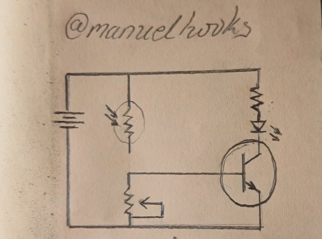
Circuit 1
This is a LED circuit powered by a battery and controled by a transistor. It has a light activated resistor that is not fully connected to the circuit. As such it may not affect the circuitry.
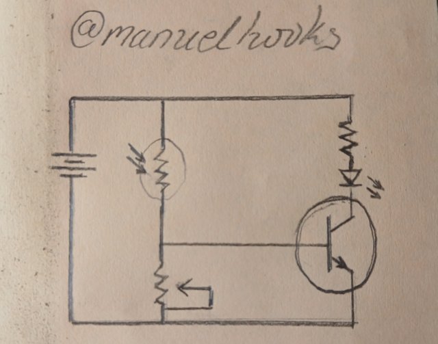
This second circurt is a LED circuit powered by a battery and controled by a transistor, like the first circuit, but in this case, the light activated resistor is fully connected such that the LED is on or off depending on the amount of light that falls on the photoresistor.
[Task 4]
7805 voltage regulator circuit
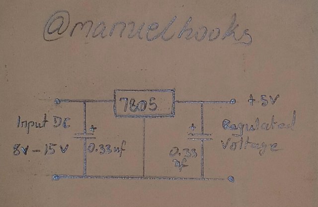
Accepts an input of 8 to 15 voltes of DC and gives out stable 5 volts as it output.
[Task 5]
4 resistors are connected in series and they are: (Brown black black Gold), (Brown black brown silver), (Red black black gold), (Brown green red gold), what are those resistors?
Brown black black Gold
10 Ω with a tolerance range of 9.5 - 10.5
Brown black brown silver
100 Ω with a tolerance range of 90 - 110
Red black black gold
20 Ω with a tolerance range of 19 - 21
Brown green red gold
1500 Ω with a tolerance range of 1425 - 1527
10 + 100 + 20 + 1500
The total resistance in series is 1630 Ω
Conclusion:
Working with circuit are very exciting, its like learning and speaking a new language made up of symbols, signs and lines. You only get better by applying yourself to it.
Invitation and contest link
I am inviting @bossj23, @josepha and @simonnwigwe
#electronicss19w3 #steemexclusive #nigeria #burnsteem25 #electronics #club5050
You have a good and interesting information in your intro but avoid making it too long like this especially when handling task in the "Electronic Academy". It almost lost interest.
You have successfully handled your task 1 in a neat and simple format. And you have highlighted the key differences between the two circuits with some great observations.
Hope other students can learn from that. However, I need to point out one thing - it's true LED is a type of diode, but it's good to be specific and clear. If it's "LED"- put it "light emitting diode ", don't just write diode. Even if you put it as "LED" that's even much better. This is in regards to your components listing on workshop 1.
Your task 2 was also done successfully with some clear interpretations and easy to understand steps to build the circuit.
**Quick question: why was the LED light dull?
You have also explained the activities of the both circuits in task 3. That was a smart observation. However, highlighting all the conponents in that circuit could be an added advantage.
You have drawn a circuit of your choice in task 4 successfully.
Your task 5 is also an excellent job.
Comment/Recommendation
Your approach to all the tasks were excellent and great effort indicating real interest in the class. And yes, electronic circuits are best enjoyed when they are built in real life. We hope to see your progress and activities in our up coming classes
Note that one of the instructions was for you to post the link of your assignment on the main lesson post!
Scores| 10/10
Thank you for the encouraging remarks.
All correction taken and effected.
Now that the resistance in the circuit is higher, power to the LED reduced and the LED become dull.
Buena respuesta, ahora la corriente encuentra mayor oposición y eso es lo que vemos reflejado en lo tenue de la luz led.
@tipu curate
Holisss...
--
This is a manual curation from the @tipU Curation Project.
Upvoted 👌 (Mana: 3/8) Get profit votes with @tipU :)
Upvoted. Thank You for sending some of your rewards to @null. It will make Steem stronger.
Another interesting post, from you again. This time around I shall try and participate sir. Last week I didn't later take part because of the needed material and how busy I was. Thank you for inviting me, and good luck to you.
TEAM 5
Your workshop for this week is so detailed. Your interest in electronics is undeniable and I've learnt from your assignment hope to participate this week too
Success sir