Introduction to Basic Electronic Components #5: Come Learn How to Build Basic Electronic Devices
Another wonderful day to talk about electronics. So far we been able to look at resistors, capacitors and diodes. If you missed the previous posts do check it out using the links below
Introduction to Basic Electronic Components #1
Introduction to Basic Electronic Components #2
Introduction to Basic Electronic Components #3
Introduction to Basic Electronic Components #4
Am glad to announce that with all that we've learnt so far we are now ready to interpret and implement a basic circuit diagram.
But before we do that I would like to bridge some gaps I left open and talk about a little of what we need to know to successfully implement this circuit.
1. Breadboards
To implement circuit diagrams one would need to have the right surface on which to place and connect his components as desired. One could just get a wood and easily do it, well such a person would require great skill to do this. But for us learners who desire to implement a circuit we would require something simpler. A surface so simple and yet could still give us what we need.
Some wise guys thought about this and designed boards that we could use to achieve our circuit implementation. They came up with breadboards, Vero boards, Printed Circuit boards (PCB) etc.
But the breadboards is what I will talk specifically on, because if we could successfully construct our circuits on a bread board and it works then using other types of boards would be piece of cake. Am just kidding, but it kinda works that way though. The breadboards are designed for temporary circuitry, as we could attach components unto it, detach them easily and use it for as many times as we want.
How do they look like
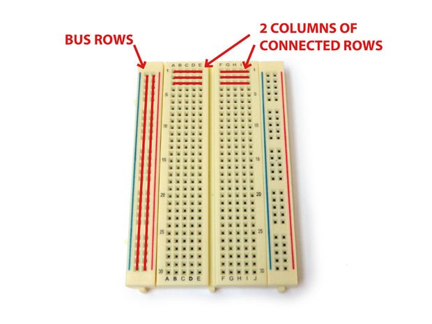
I don't really know why they are called bread boards but I guess it because they have holes like breads. Not really sure but do breads have holes?
The breads sorry holes on the bread boards allow us to attach our electronic components temporarily. You can attach your LED to it as shown below
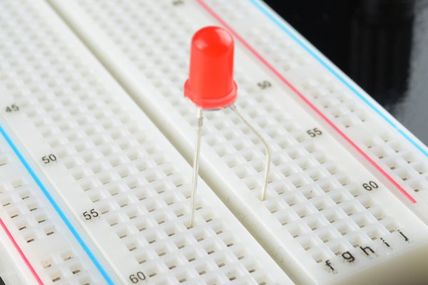
There is no particular convention used to attach electronic components to a breadboard but understanding how the holes are connected will serve as a guide when connecting yours.
From the diagram above. The two long columns (bus rows) from end to end are usually used as power rails, that is, they are used to connect the battery terminal or more preferable, that is where we connect our battery. While the other short rows placed side by side are used to attach our components. At the center the rows are parted, this is where we attach an IC (Intergrated Circuits).
2. Voltage Dividers
If a voltage Vin is placed across two resistors in series as shown below, an output Voltage Vout can be tapped from R2 with reference to Gnd.
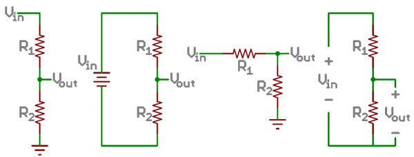
The output voltage Vout is equal to the potential difference across R2 and is given by the formula below
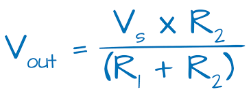
This simple combination of resistors can be used to control the output voltage Vout by varying the resistors in series.
If the resistor R2 is equal to R1, Vout would be half the input voltage Vin. And if the resistor R2 is far greater than R1 the potential difference across R2, Vout, would increase and its value close to Vin.
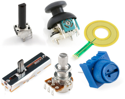
Individual resistors could be used to create a voltage divider, but most a times potentiometers are more preferred. A Potentiometer is a variable resistor which can be used to create adjustable voltage dividers because as we are varying the resistance R1 and R2 we vary the output voltage Vout.
Potentiometers come in all sorts of forms. Common potentiometers used are shown below
The Circuit diagram we will be implementing is shown below
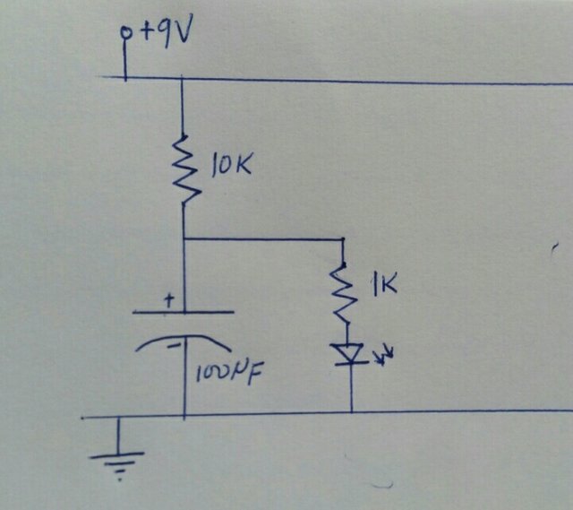
This circuit is ideal for testing the time-dependent resistor capability of a capacitor we talked about in the previous post
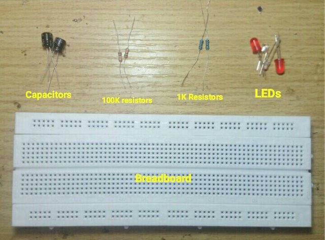
Materials needed include:
- 9V battery
- 1K resistor
- 10K resistor
- 100uF capacitor
- Breadboard
How to connect the curcuit
Step 1
Connect the battery as shown
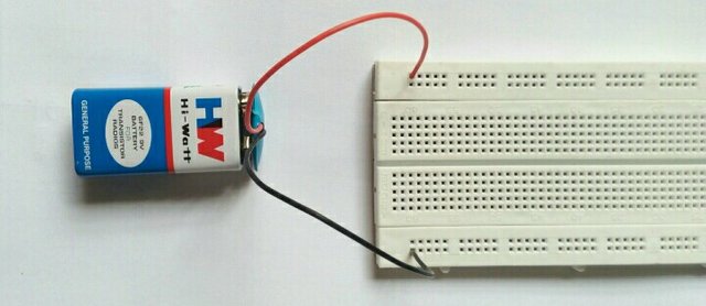
Step 2
Connect the 100K sorry 10K Resistor, one leg to the power rail and the other leg as shown
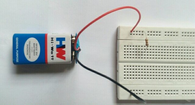
Step 3
Connect the 100uF capacitor in series with the resistor as shown below leaving space to tap Vout
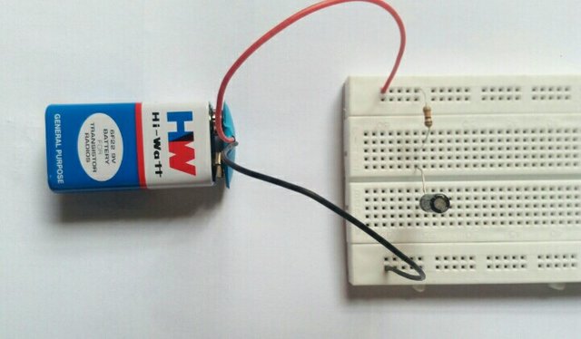
Step 4
Connect the 1K resistor between the 100K resistor and the 100uF capacitor as shown below
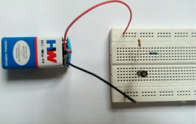
Step 5
Connect the LED as shown below. Endeavor not connect the two legs of the LED on the same row, this will cause a short circuit.
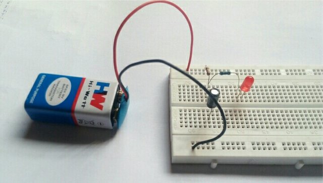
Step 6
Using jumper wires connect the second leg of the capacitor and the LED to ground (negative terminal) as shown below
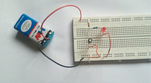
At the initial time when the circuit is complete the capacitor is not charged and the resistance of the capacitor is close to 0Ω and therefore Vout is also close to 0V, which is too low to power the LED. Thats why the LED is off.
After some time the capacitor starts charging and resistance of the capacitor increases causing Vout to increase, turning the LED on. The LED keeps getting brighter until the capacitor is fully charged. As shown below
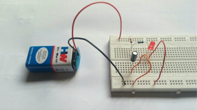
The value of the resistor 1, in this case 10K, determines how long before the capacitor is fully charged.
For those who would like to try, below is another circuit which does the reverse of the circuit we just implemented.
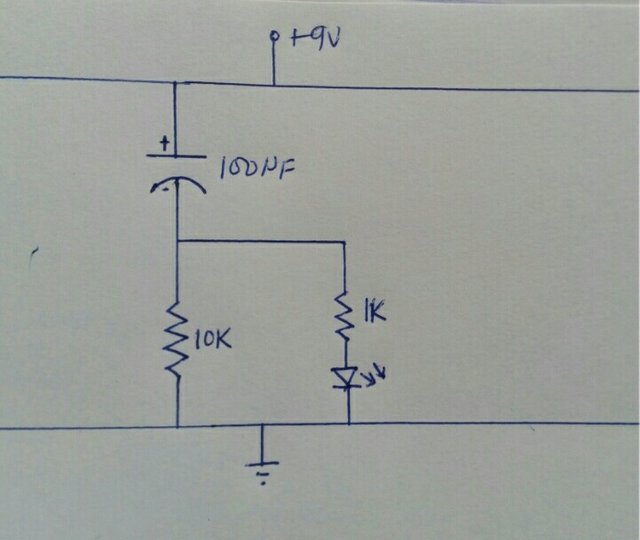
I guess this it for now. As the saying goes *Practice makes perfect *. Until next time
Reference:
Image Credit:
- Image 1 from pixabay.com
- Image 2 Instructables
- Image 3 and 5 from sparkfun
- Image 4 from Ohms Law Calculator
- Other images are mine

Great work my friend.... Loved it
@originalworks
The @OriginalWorks bot has determined this post by @kenadis to be original material and upvoted(1.5%) it!
To call @OriginalWorks, simply reply to any post with @originalworks or !originalworks in your message!