Introduction to Basic Electronic Components #2: Come Learn How to Build Basic Electronic Devices

Yet another day to explore the basic electronic world. Today I will dive deeper, I will present one or two electronic components and how they function in an electronic circuit depending on how long the post gets.
I wouldn't want my post to be that lengthy and discouraging. I want the knowledge to be learnt bit by bit in such a way that readers won't miss the basic point.
If you missed yesterday's post which explains the very basics you need to know before jumping into electronics do well to check it out.
The first one on my list is.... Can you guess? ... Well it's The Resistor
The Resistor
As can be easily deduced from the name resistors are electronic devices that that oppose the flow of current.
Resistors basically don't have much work to do but to resist current flow. But not withstanding they are one of the most essential electronic components we have.
Why would I want a device that just does nothing but to resist the flow of current? Don't I want current to flow freely so that I can power my device?
But the importance of resistors is obvious, we need their resistance, or would you prefer to have a current of 2A flow through your device rated 500mA? Still don't know what would happen to the device? Well no need for speculation, just go on, power the device with 2A. What can you see? Or am I the only one seeing the device producing smoke?
Okay, if am the only one seeing the smoke, no problem. I only just hope you saw it too. From the above we could say the first importance of a resistor would be to protect a circuit from excess current flowing. Resistors are also used as voltage dividers, sensors as in the case of a Light Dependent Resistor (LDR) etc.
What do they look like?
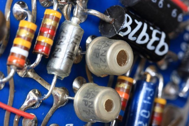
Basically they look like very small cylindrical objects with leads at both ends as shown below

Resistors are measured by their power and ohm rating. As you would have noticed, apart from the general body color of the resistor, there is also present 4 small bands of different colors on the resistor.
The bands of color on the resistor indicates and helps one calculate the value of the resistance of a particular resistor in view.
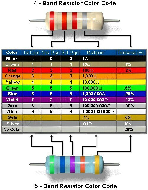
The first two color bands represent the resistor value, the third color band represents the multiplier and the fourth band represents the tolerance of the resistor.
Different resistors have different color bands and calculating the resistance can get confusing and for this reason some wise guys took it upon themselves to develop a table which summarised the color interpretation. The table is given below:

Let's calculate the value of one or two resistors. Before that I would like to mention that the color bands are read from left to right usually towards the gold or silver band. Now for the example:
Resistor A has colors - red, green, orange and gold while,
Resistor B has colors - black, yellow, blue and silver.
From the table,
Resistor A would have: 2(red) 5(green) X 1000(orange) = 25 000 or 25K for short with tolerance of +/- 5%
and
Resistor B would have: 0(black) 6(blue) X 1000000(blue) = 6,000,000 or 6M for short with tolerance of +/- 10%
Sometimes you may have a resistor with as many as 5 bands, nonetheless the procedure for calculation of resistance is still the same, all you have to do is to follow the table. But the resistors with 4 color bands are more common and readily available.
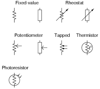
In electronic circuits resistors are represented using symbols. The symbol to be used generally depends on the function and state of the resistor in the circuit - Can the value of the resistor be changed using a knob? , does the value of the resistor change with the effect of light, heat or any other physical factor? Common resistor symbols in electronic circuits are shown below

Resistor Configuration
Resistor just like Batteries as we discussed in the previous post, can be connected in either series or parallel. Connecting them in series or parallel will result in different Equivalent Circuit Resistance (RT)
The Equivalent Circuit Resistance (RT) depending on the configuration can be calculated using the formula below:
For Series Equivalent Circuit Resistance (RT) is given as
RT = R1 + R2 + R3 + ... +RnFor Parallel Equivalent Circuit Resistance (RT) is given as
1/RT = 1/R1 + 1/R2 + 1/R3 + ... + 1/Rn
Well this it for now. Thanks for taking your time to read through, I hope you enjoyed every bit of it. Don't forget the formulas above because they are one of the very basic formulas we should always remember when considering electronics and circuits in general.
Stay tuned and don't forget to drop your views and comments below as they will encourage me and guide me on how to improve my posts.
Until next time
Reference:
Mostly my work from years of study and some citing from Wikipedia
Image Credit:
- Image 1 from pixabay.com
- Image 2 from instructables
- Image 3 from Live Watch
- Image 4 from All About Circuits

you made my day
Thanks
@originalworks
The @OriginalWorks bot has determined this post by @kenadis to be original material and upvoted(1.5%) it!
To call @OriginalWorks, simply reply to any post with @originalworks or !originalworks in your message!