Control of VSC:Part 1⚡️⚡️
Design of control strategy in 3-ph (abc)- frame is much more difficult as well as a more complex compared to αβ-frame. As it reduces the control vector from three to two. It provides a decoupled control for active and reactive power. The decoupled control of power exchange between VSC and AC system can be realized by αβ-frame. But it has certain demerits as its control variables, feedback and feed forward signal are sinusoidal, which demands more complex control strategy. dq frame is having all merits of αβ-frame along with merits to have a control variable as DC quantities at steady state. It provides a simpler control strategy for controlling independently active and reactive power as control variables are DC signals
Parameters like modulation index ‘m’, phase angle δ and frequency ωo can be controlled using an appropriate control strategy. Control over reactive power a=can be achieved by controlling the AC voltage which is the result of controlling modulation index. System AC voltage is being compared with reference and provided to reactive power controller. AC voltage at converter terminal is resulting from PWM modulation index. Hence lower the AC voltage magnitude at converter bus, converter absorbs reactive power and higher the AC voltage at converter bus, delivers the reactive power to grid .
Frequency control can be achieved by controlling the frequency of firing sequence. Active power can be controlled by controlling the phase angel δ, and DC link voltage.
To have a control over active power and reactive power independently there are two methods, voltage mode control and current mode control. Current mode control provides over current protection to VSC but the same is the drawback of voltage mode control. In this the line current is tightly controlled by a dedicated control scheme. Then a real and reactive power is controlled by controlling the phase angle and amplitude of the VSC line current with respect to AC side voltage .
Current control mode is used in VSC-HVDC control strategy for operation. Inner current control loop resided in the VSC control strategy. It receives signal from outer control loop (AC voltage controller, reactive power controller, DC voltage controller and active power controller) compared to its reference value to generate a reference voltage vectors and hence the control action.
The control can be achieved by transforming voltage and current vectors from abc to dq-frame.
abc to dq- transformation:
To achieve the above transformation, we need to transform abc- frame to αβ- frame and then to dq- frame. In αβ- frame the feed-forward, feed-back, and control signals are sinusoidal function of tine. To process the DC signal rather than AC signal for control purpose it is need to transformation αβ- frame to dq-frame.
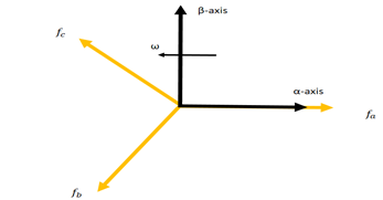
Clarke transformation converts the three phase balanced quantities to 2 phase balanced orthogonal quantities.
Transformation matrix is given below

Where Tαβo is the transformation matrix
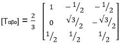
Where f represents the voltage, current, flux linkage and electric charge.
αβ- Frame to dq-Frame transformation:
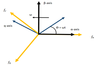
Fig2: αβ- Frame to dq-Frame
Phase locked loop (PLL):
It is a common method of finding the AC side voltage phase angle to synchronize the delivered power. There are several methods of detecting phase angle. Those are zero crossing detection, filtering grid side voltage and using PLL technique. PLL is having a phase tracking mechanism where a synchronized output with input phase and frequency. This mechanism is used to synchronize current and AC side voltage to get a unity power factor operation. A 3phase AC voltage input is given to PLL model. This model is implemented on dq-frame by controlling q axis voltage i.e. Uq to zero. PI controllers are used to achieve this purpose
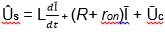
Dynamic model of AC side VSC:
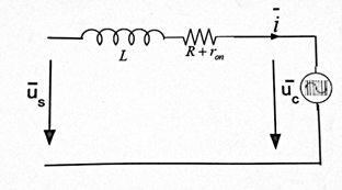
Where Ūs and Ūc are grid side AC voltage and converter bus AC voltage respectively. L and (R+ ron) are inductance and resistance of both inductor and converter switches respectively.
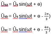
WhereŪs is peak value of line to neutral voltage, ω is the angular frequency of the AC system, ɵ is the initial phase angle of the system.
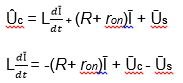
Dynamics of AC side of the VSC system:
By reversing the current direction as VSC interact with AC system and exchanging power with AC system. The equation last is modified to,
Writing the above equation , implementing it in dq-frame by substituting
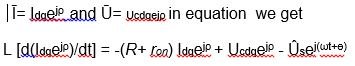
WhereŪs= Ūsej(ωt+ɵ) is the space phasor representation of AC grid voltage.
Decomposing the above equation into its real and imaginary components we have
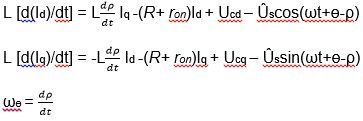
Equations described in are non-linear equation. Control inputs are ωɵ, Ucd and Ucq. State variables that to be controlled are Id, Iq and ρ. Assuming initial condition of ρ is zero. Hence ωɵt = 0; the equation and are described below as a decoupled first order system.
For VSC system dq-frame can be realized by selecting ωɵ and ρ. If ωɵ= ω and
ρ(t) = (ωt + ɵ), then last two Equation takes the form of
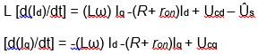
are second order linear equations. It is excited by an input Us. Where Ucd, Ucq, Id and Iq are DC variables in steady state.
Control structure of VSC:
Control of VSC is aiming towards the control of both active and reactive power. Different control strategy are used for control purpose. Direct control and vector control methods are used. Which are basically a voltage controlled VSC and current controlled VSC respectively .
Voltage controlled method is to control the real and reactive power by directly controlling the phase angle and converter output voltage. But in case of current control scheme converter act as like a controlled current source. Where the current vector tracks the reference current vector.
Advantages of current mode control over voltage mode control are
- • Short-circuit protection to converter as it tightly controls the converter line current.
• Power quality improves as it is less affected by grid harmonic and disturbances.
• Decoupled control of real and reactive power.
Reference
- 🌟Yazdani. "Electronic Power Conversion, Voltage-Sourced Converters in Power
Systems”, 01/25/2010.
Wiley-IEEE Press
- 🌟V. Sood, HVDC and Facts Controllers - Applications of Static Converters in Power Systems. Kluwer Academic Publishers, 2004. ISBN 1-4020-7891-9. springer.com
- 🌟Asplund. G., Eriksson. K, Svensson, K: “DC Transmission based on Voltage Source Converters” , CIGRE SC14 Colloquium on HVDC and FACTS in South Africa, 1997. abb.com
Congratulations @paultarpan! You have completed the following achievement on Steemit and have been rewarded with new badge(s) :
Click on the badge to view your Board of Honor.
If you no longer want to receive notifications, reply to this comment with the word
STOPTo support your work, I also upvoted your post!
Do not miss the last post from @steemitboard:
SteemitBoard World Cup Contest - The results, the winners and the prizes
Congratulations @paultarpan! You have received a personal award!
Click on the badge to view your Board of Honor.
Do not miss the last post from @steemitboard: