Physics - Electromagnetism - AC Transformers
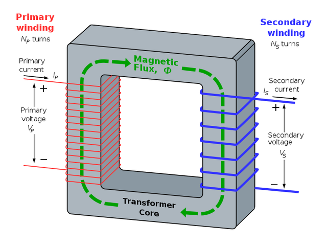
Image source: https://en.wikipedia.org/wiki/Transformer#/media/File:Transformer3d_col3.svg
Introduction
Hello it'a me again @drifter1! Today we continue with the Electromagnetism series to talk about AC Transformers. Such transformers are based on a lot of things that I covered through-out the series, but the most important ones are for sure: current, voltage, magnetic flux, electromagnetic induction and the alternating current that we cover/covered now! So without further do, let's start!
How they work
Transformers are electrical devices based on the principles of Electromagnetic Induction and transfer energy from one electric circuit to another, without changing it's frequency. The most important thing to remember about transformers is that they don't generate electrical power! Transformers either increase or decrease AC voltage by changing the magnitude of current by doing so.
The four primary parts of a basic transformer are:
- Input Connection
- Output Connection
- Windings or Coils
- Core
Cores can be of two types:
- Core Type -> the windings surround the laminated core
- Shell Type -> the windings are surrounded by the laminated core
Fast explanation of the working principle:
When an input voltage is being applied to the primary winding, alternating current starts flowing in this winding. This changing current of course produces a changing magnetic field that affects the transformer core (changing current is one of the sources of magnetic fields). As this magnetic field cuts across the secondary winding, alternating voltage is produced in the secondary winding. The output voltage is closely binded to the ratio between the number of actual coils of wire in each coil, something that also determines the type of transformer we are talking about. Something very important is that:The ratio between the output voltage and input voltage is the same as the ratio of the number of turns between the two windings.
More specifically, the output voltage is greater than the input voltage if the secondary winding has more turns of wire than the primary winding. When the output voltage is stepped up (greater) we talk about "step-up transformers". When the output voltage is stepped down we talk about "step-down transformers".
The following mathematical formula shows us exactly that:

Where:
- Vinput and Voutput are the voltages at the input and output
- Ninput and Noutput the number of turns at the input and output

Configurations
There are lots and lots of different configurations for both single-phase and three-phase tranformers. Each configuration is useful in different applications. Let's get into some:
- Single-Phase Power - Such transformers are often used to supply power for residential lighting, receptacle, air-conditioning and heating needs. They can be made even more versatile by having both the primary and secondary winding made in two equal parts. These two parts can be reconnected in series or parallel configurations.
- Three-Phase-Power - Power may be supplied through a three-phase circuit that contains three single-phase transformers. Such a configuration is more economical to use. The unique arrangement also saves us iron.
- Delta and Wye Defined - Delta and Wye are Greek letters that represent the way at which the conductors on the transformers are configured. In a Delta connection, the three conductors are connected end to end in a triangle or delta shape. For a wye, all the conductors radiate from the center, meaning they are connected at one common point. Both of these configurations are three-phase-power.
- Three-phase Transformers - Three-phase transformers consist of six windings: three primary and three secondary. Those six windings are connected either delta or wye with each other. But, they don't have to be connected in the same configuration in the same transformer. THe actual configuration depends upon the application.
Types
Let's now get into some Types of transformers...
- Power Transformer - Such transformers are used to couple electrical energy from a power supply line to a circuit system, or one or more components of the system. A power transformer that is used with solid state circuits is called a rectifier. Rectifiers change AC to DC by electronic circuitry. Only half of the AC energy is being converted to "similar" DC. The rest is turned into heat. That's why Adapters get warm. A power transformer's rating is given in terms of the secondary's maximum voltage and current-delivering capacity.
- Distribution Transformer - Such pole-type distribution transformers are used to supply relatively small amounts of power to residences, and also at the end of electrical utility delivery systems.
- Autotransformer - A special type of transformer that consists only of a single, continuous winding that provides either a step-up or a step-down function. This of course differentiates it from conventional two-winding transformers. The autotransformer's windings are therefore, both electrically and magnetically interconnected. Such transformers are of course much cheaper, have greater regulation (less voltage drops) and also a greater efficiency. Furthermore, such transformers are also considered unsafe for ordinary distribution circuits, as high-voltage primary circuits are connected directly to low-voltage secondary circuits.
- Isolation Transformer - Another unique transformer. Such transformers have a 1:1 turn's ratio and therefore do not step up or step down. They are used is as a safety device. They can isolate the grounded conductor of a power line from a portion of circuit load, therefore reducing the danger or shock if contact is made across the secondary winding. Technically all "true" transformers, wheter they are used to transfer signals or power, are isolating. The primary and secondary windings are never connected by conductors, but only by induction. But, only those with the primary purpose of isolation are being considered Isolation Transformers.
- Instrument Transformer - Another interesting use-case of transformers is as an instrument of measuring high values of current or voltage. To measure such high currents/voltages we don't use low-range measuring instruments, but also specially-constructed instrumetnt transformers. Such transformers are also called accurate ratio transformers as they transform at an accurate ratio, allowing an attached instrument to gauge the current or voltage without actually running the full power through the intstrument. We have two types of instrument transformers: Current and Potential/Voltage that do as they name suggests.
- DC transformers - DC voltage cannot be changed in the same way as AC, because DC current doesn't change the magnetic field as AC current does. That's why AC has won over DC as form of electricity/electrical energy. But, still special circuitry that acts as an DC transformer, has been build by electrical engineers.
- Potential-Voltage Transformer - Such transformers are extremely accurate step-down transformers. They are normally used together with a standard 120-volt voltmeter. The user can determine the voltage on the "high" side by the ratio of transformers that usually is: "10:1", "20:1", "40:1", "80:1", "100:1", "120:1" or even higher. Potential transformers are very similar to standard two-winding transformers, except that they can handle a very small amount of power. To provide better accurancy they are always Shell-type. Last but not least, they are designed to monitor single-phase and three-phase power line voltages in power metering applications.
- Current Transformer - Such transformers have a primary coil of one or more turns of "heavy" wire. They are always connected in series to the circuit in which current is to be measured. The secondary coil consists of many turns of "fine" wire, that must always be connected across the ammeter terminals. The secondary of a current transformer is never open-circuited, because the primary one is not connected to a constant source (there is a wide range of possible primary voltages). Therefore, the secondary must always be closed-circuited to react with the primary and to prevent the core from becoming completely magnetized (something that would cause accurancy-loss). Clamp-on ammeters work in a similar way.
Voltage Transformer
What we analyzed at the beginning was basically a Voltage Transformer, even though Current Transformers are based on the same principle. As we said previously, the two coil windings of a single-phase voltage transformer are not electrically but magnetically linked through Electromagnetic Induction. Such a transformer can either "increase" or "decrease" the voltage from the primary to the secondary winding. That's why we have step-up and step-down transformers. There also exists a third "type" which is known as a Impedance Transformer. Such transformer keep the current, voltage and power at the output identical to the input. Such transformers are basically Isolation Transformers. To change the voltage difference between the primary and secondary windings, we have to change the number of coil turns in the primary winding (Np or Ninput) in respect to the number of coil turns in the secondary winding (Ns or Noutput).
Transformers are basically linear devices, which means that we can find a ratio between the number of coils in the primary coil divided by the number of turns in the secondary coil (as we already told before). This ratio is known as the "turns ratio" (TR). TR's value dictates the operation of the transformer and therefore the voltage available on the secondary winding. From all this we see that this ratio is of great importance. This ratio of course has no units and is mostly written in the form: "3:1" or "3-to-1", which for example means that for 3 volts of the primary winding there will be 1 volt in the secondary winding. The ratio between the number of turns (TR) is equal to the ratio of the resulating voltages. So, transformers are all about the following ratio: 
At this equation we of course assume an ideal transformer with equal phase angles (Φp = Φs), between the primary and secondary winding. Also note that the order of the numbers matters, cause a "3:1"-transformer is different to a "1:3"-transformer; Here the first one defines a step-down transformer from 3 to 1 volts, whilst the other a step-up transformer from 1 to 3 volts.
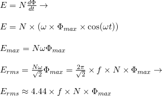
Another interesting topic that we should cover is the produced emf in the secondary winding. The magnetic flux Φ of course varies sinusoidally following the expression: Φ = Φmax sinωt. Having a coil of N turns the induced emf (E) therefore is: 
Where:
- f is the flux frequency (that we got from ω = 2πf)
- N the number of coil windings/turns
- Φ the amount/magnitude of flux

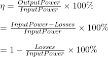
Of course: Input, Output and Losses are all expressed as units of power (watt)!
When talking about transformers, the primary watts are called “volt-amps” or VA, to differentiate them from the secondary watts. Using this we can define the so called Transformer Efficiency Triangle:

Based on the triangle at: https://www.electronics-tutorials.ws/transformer/transformer-basics.html
From this triangle we have that the output wattage W is:

Current Transformer
A type of instrument transformer that is designed to produce an alternating current in it's secondary winding that is proportional with a constant ratio to the current in it's primary. As we already saw before such transformers reduce high voltage currents to much lower value and so provide a convenient way of monitoring the current flow in an AC transmission line using standard ammeters. The principal operation of a basic current transformer differs slightly to that from an ordinary voltage transformer. We already said that such transformers are "series transformers", cause they need to be connected in series. Unlike in voltage transformers the primary current of a current transformer is being controlled by an external load.
There are three basic types of current transformers:
- Wound - The transformer's primary winding is physically connected in series with the conductor that carris the measured current flowing in the circuit. The secondary current depends on the turns ratio (TR) of the transformer.
- Toroidal - Such a transformer doesn't contain any primary winding. Instead it contains a line that carries current flowing in the network through a window or hole. Some of them have a "split core" that allows it to be opened, installed, closed, without having to disconnect the circuit to which they are attached on.
- Bar - This type of current transformer uses the actual cable or bus-bar of the main circuit as the primary winding (something equivalent to a single turn). There are fully insulated from the high operating voltage of the system and are usually bolted to the current carrying device.
Such transformers must satisfy a amp-turn equation (in respect to the voltage-turn equation of voltage-transformers). The turn ratio (TR) therefore now is equal to the ratio of the secondary to the primary current (opposite) as following:

This gives us a secondary current equation of the form:

Current Transformers (CTs) can also be found as Handheld devices. Such devices can be used for detecting overcurrent, undercurrent, peak current, or the average current conditions. Of course the transformers that we covered till now where all single-phase ones and so note that 3-phase transformers for current exist, having star or delta configurations to produce even larger power transformers....
REFERENCES:
- http://www.galco.com/comp/prod/trnsfmrs.htm
- https://www.school-for-champions.com/science/ac_transformers.htm#.W4j6YOj7QaY
- https://www.electronics-tutorials.ws/transformer/transformer-basics.html
- https://www.electronics-tutorials.ws/transformer/current-transformer.html
Mathematical equations that I had in this post where drawn using quicklatex!
Previous articles of the Electromagnetism series
Here we only have the previous two "chapters" and the current one....
Electromagnetic Induction:
Electromagnetic Induction and Faraday's law -> Electromagnetic Induction, Experiments, Faraday's law
Motional Electromotive Force (Emf) -> Motional Emf, Faraday's law and motional emf, generalization
Lenz's law and Induced Electric fields -> Lenz's law, Induced Electric Fields
Eddy Currents and Applications -> Εddy currents, applications (brakes, testing, others)
Maxwell's equations -> What they are, each equation analyzed separately
Electromagnetic Induction exercises -> examples all around Electromagnetic Induction
Mutual and Self Induction:
Mutual Inductance -> Mutual Inductance, applications
Self Induction -> Self Induction, Lenz's law, Inductance of a Coil
Magnetic Energy Density -> Energy stored in a magnetic field (or inductor), Magnetic energy density, Coaxial Cable Inductance Example
R-L circuits -> R-L circuit energizing, de-energizing, Characteristic time constant
L-C circuits -> L-C circuit, oscillations, energy cases, applications
R-L-C circuits -> R-L-C circuit, oscillation, applications
Mutual and Self Induction exercises -> examples all around Mutual and Self Induction
Alternating current:
Getting into Alternating current -> Phasor diagrams, Alternating current, Average (RMS) current and voltage, Differences, Advantages/Disadvantages
Electric Reactance in AC circuits -> Resistors, Inductor and Capacitor Reactance in AC circuits
Series R-L-C circuits Impedance -> Series R-L-C circuits, Phasor Diagrams, Impedance
Power in AC circuits -> DC Resistive circuit, Power in AC circuits (resistive, reactive), Power Factor
Resonance in Series R-L-C circuits -> Series R-L-C circuit, Series Resonance
Resonance in Parallel R-L-C circuits -> Parallel R-L-C circuit, Parallel Resonance
Final words | Next time
And this is actually it for today's post! Next time we will get into exercises/examples all around Alternating current (AC)...like we do always when finishing a chapter/topic of Physics.
Keep on drifting!


Hi @drifter1!
Your post was upvoted by utopian.io in cooperation with steemstem - supporting knowledge, innovation and technological advancement on the Steem Blockchain.
Contribute to Open Source with utopian.io
Learn how to contribute on our website and join the new open source economy.
Want to chat? Join the Utopian Community on Discord https://discord.gg/h52nFrV
Just a little Note. I write the articles through busy.org and more specifically directly in HTML, which means that I refresh my knowledge around HTML and Web Development in general again.
So, be prepared!
After Electromagnetism we will of course continue with other branches of Physics, get back into Mathematics stuff that I promised to make, revive the Compiler series...but most importantly start with a "new" Web dev series, that will cover all the steps for implementing something specific using HTML, CSS, Javascript, PHP and also a SQL Database. Computer architecture, VLSI design, Artifical Intelligence and so on..will also be in my list for the following months of "Steeming"!
*crickets *
Congratulations! Your post has been selected as a daily Steemit truffle! It is listed on rank 13 of all contributions awarded today. You can find the TOP DAILY TRUFFLE PICKS HERE.
I upvoted your contribution because to my mind your post is at least 8 SBD worth and should receive 165 votes. It's now up to the lovely Steemit community to make this come true.
I am
TrufflePig, an Artificial Intelligence Bot that helps minnows and content curators using Machine Learning. If you are curious how I select content, you can find an explanation here!Have a nice day and sincerely yours,

TrufflePigThis post has been voted on by the steemstem curation team and voting trail.
There is more to SteemSTEM than just writing posts, check here for some more tips on being a community member. You can also join our discord here to get to know the rest of the community!