Physics - Electromagnetism - Electric Reactance in AC circuits
Image source: http://electriciantraining.tpub.com/14181/css/Effect-Of-Frequency-On-Capacitive-Reactance-16.htm
Introduction
Hello it'a me again @drifter1! Today's article is yet another article from the Electromagnetism series, where we will now continue with Electric Reactance in AC circuits! Knowing what Resistors, Capacitors and Inductors are might be very helpful, which means that I highly suggest you to go read about them...following some steps back from this article :P
So without further do, let's get started!
Resistors in AC circuits
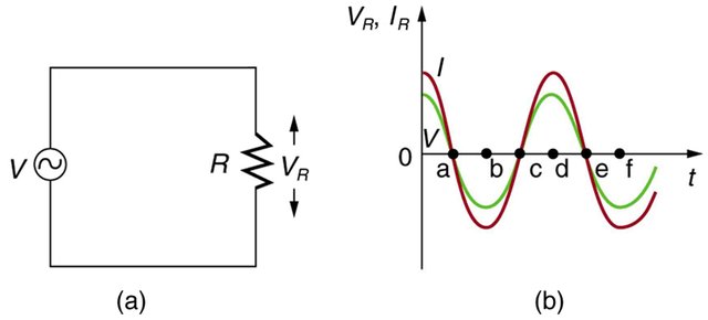
In AC circuits voltage and current are "in phase" inside of resistors. There is no frequency dependence to the behavior of "plain" resistance in circuits. For a series circuit of a AC voltage source with a resistor the graphs of current and voltage across the resistor as functions of time will be exactly in phase and will only have different magnitudes. They also represent different quantitites either way. So to sum up, when sinusoidal voltage is applied to a resistor, the voltage is exactly in phase with the current, which means that they have a 0 phase angle/difference.
This can be seen clearly in the following Figure:
Image source: https://opentextbc.ca/physicstestbook2/chapter/reactance-inductive-and-capacitive/
Electric Reactance
In electronic circuits we define Reactance as the opposition of a circuit element to a change of electric current or voltage, due to that element's inductance or capacitance. Electric fields resist the change of voltage on the element, whilst magnetic fields resist the change of current. Reactance and electrical resistance are similar in notion, but differ in a lot of aspects. As we already know from previous articles, capacitance, inductance and resistance are inherent properties of an element. Until now we only talked about direct current (DC) where the reactive effects of them are not exhibited to, cause direct current is constant and so the conditions of the circuit don't change. Therefore, reactance only makes sense in AC currents. This reactance depends on the frequency and so is only constant for a constant AC frequency. The SI unit of Rectance is the Ohm (Ω), which is the same as the one we are using for resistance!
For our analysis that follows we will consider:
- ideal resistors with zero reactance
- ideal inductors and capacitors that consist entirely of reactance
The common symbol that is being used for Reactance is 'X'.
Let's sum up everything that we talked about till now. Reactance is a measure of the opposition of capacitance and inductance on current, varies with the frequency of the electrical (AC) signal and is measured in Ohm's (Ω).
We can clearly see that there are two types of reactance:
- Capacitive reactance (Xc)
- Inductive reactance (XL)
The total reactance (X) of a circuit is the difference between the two:
Let's now analyze each one more...
Capacitors and Capacitive Reactance
Consider a capacitor connected direcly to an AC voltage source (series connection). The resistance of such circuits is so small that it has a negligible effect compared to the effect of the capacitor and so we assume zero resistance. The voltage and current across the capacitor can again be graphed as function of time. Starting of with the voltage across the capacitor being maximum, the current is of course zero at this point, because the capacitor is fully charged and so stops the flow of current. While the voltage drops the current becomes negative as the capacitor discharges. At some point the capacitor will be fully discharged (Q = 0) and so the total voltage across it is zero and the current is maximum. Continuing on the voltage of the capacitor reverses and at some point reaches the most negative value having zero current flow. When sinusoidal voltage is applied on a capacitor, the voltage follows the current by one-fourth of a cycle or has a 90 phase angle.
As sinusoidal waveforms the voltage and current can be noted as:
Let's get into this ability of the capacitor that even let's it fully stop current altogether when fully charged even more in-depth. As AC voltage is applied there is an rms current that is being limited by the capacitor. Considering this effective reactance of the capacitor, noting the rms current as I and thinking of the capacitive reactance as an effective resitance, Ohm's law can of course be applied giving us:
where:
- I is the rms current
- V is the rms voltage
- Xc is the capacitive reactance
Analysing the circuit using Kirchhoff's rules and Calculus we end up with the following mathematical formula/expression that gives us the capacitive reactance of a capacitor of capacitance C:
We can see that Xc is inversely proportional to the capacitance C, which means that a larger Capacitor stores greater charge and so greater current can flow through the circuit. Xc is also inversely proportional to the frequency. The greater the frequency, the less time there is to fully charge the capacitor!
Inductors and Inductive Reactance
Let's now suppose an inductor that is directly connected to an AC voltage source. We again assume negligible resistance. Analyzing the voltage and current through the inductor we will now see something pretty similar. Let's again start with the voltage at maximum. At this point the current of course is zero. After closing the circuit the voltage starts dropping and the current rises to it's peack exactly when the voltage reaches zero. Continuing on the current starts dropping and so the voltage becomes negative. When the current becomes zero the voltage will have reaches the most negative value. Then the current becomes negative, following the voltage. From all this we can see that the voltage leads the current by one-fourth of a cycle or 90 phase angle.
As sinusoidal waveforms the voltage and current can be noted as:
As we know from the series till now, inductors oppose the change in current and so this explain the "lagging" of current behind voltage. From Faraday's law we know exactly how much current is being induced back from the emf [V = -L(dI/dt)]. Considering the effective resistance of the inductor to AC as the inductive reactance and noting the rms current I again, Ohm's law gives us again:
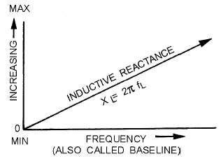
Doing some Calculus and using Kirchhoff's loops rule we finally end up with the following mathematical formula/expression for inductive reactance:
We can see how XL is proportional to L and the frequency. This means that a greater induction causes a greater resistance to change, and that a greater frequency means a greater change in current. And so dI/dT is large for large frequencies.
REFERENCES:
- https://opentextbc.ca/physicstestbook2/chapter/reactance-inductive-and-capacitive/
- http://units.wikia.com/wiki/Electrical_reactance
- https://electronicsclub.info/impedance.htm
- https://www.electronics-tutorials.ws/accircuits/ac-capacitance.html
- https://www.electronics-tutorials.ws/accircuits/ac-inductance.html
Mathematical equations that I had in this post where drawn using quicklatex!
Previous articles of the Electromagnetism series
Here we only have the previous two "chapters" and the current one....
Electromagnetic Induction:
Electromagnetic Induction and Faraday's law -> Electromagnetic Induction, Experiments, Faraday's law
Motional Electromotive Force (Emf) -> Motional Emf, Faraday's law and motional emf, generalization
Lenz's law and Induced Electric fields -> Lenz's law, Induced Electric Fields
Eddy Currents and Applications -> Εddy currents, applications (brakes, testing, others)
Maxwell's equations -> What they are, each equation analyzed separately
Electromagnetic Induction exercises -> examples all around Electromagnetic Induction
Mutual and Self Induction:
Mutual Inductance -> Mutual Inductance, applications
Self Induction -> Self Induction, Lenz's law, Inductance of a Coil
Magnetic Energy Density -> Energy stored in a magnetic field (or inductor), Magnetic energy density, Coaxial Cable Inductance Example
R-L circuits -> R-L circuit energizing, de-energizing, Characteristic time constant
L-C circuits -> L-C circuit, oscillations, energy cases, applications
R-L-C circuits -> R-L-C circuit, oscillation, applications
Mutual and Self Induction exercises -> examples all around Mutual and Self Induction
Alternating current:
Getting into Alternating current -> Phasor diagrams, Alternating current, Average (RMS) current and voltage, Differences, Advantages/Disadvantages
Final words | Next time
And this is actually it for today's post! Some more stuff could have been mentioned here, but I will make separate posts about R-L-C circuits later on, and so avoided those topics. Next time we will get into Series R-L-C circuits, but this time from the AC circuit point of view!
Keep on drifting!


This post has been voted on by the steemstem curation team and voting trail.
There is more to SteemSTEM than just writing posts, check here for some more tips on being a community member. You can also join our discord here to get to know the rest of the community!
Hi @drifter1!
Your post was upvoted by utopian.io in cooperation with steemstem - supporting knowledge, innovation and technological advancement on the Steem Blockchain.
Contribute to Open Source with utopian.io
Learn how to contribute on our website and join the new open source economy.
Want to chat? Join the Utopian Community on Discord https://discord.gg/h52nFrV