Introduction to Basic Electronic Components #8: Come Learn How to Build Basic Electronic Devices
Season greetings to all steemians. Just a few days to Christmas. I want to sincerely thank all those people who have made the few days I have been on steemit enjoyable and rewarding. I say thank you again and a Merry Christmas
Back to electronics. I haven't been consistent with posting lately, I have been occupied with my project work. Nonetheless I didn't forget about you guys and that's why for today we will look at transistors. If you missed the previous posts do check it out using the links below
Introduction to Basic Electronic Components #1
Introduction to Basic Electronic Components #2
Introduction to Basic Electronic Components #3
Introduction to Basic Electronic Components #4
Introduction to Basic Electronic Components #5
Introduction to Basic Electronic Components #6
Introduction to Basic Electronic Components #7
What are transistor?
Transistors are more advanced application of semiconductors. They function kind of similar to diodes except with more functions
Transistors are three legged electronic device that are basically used as switches or amplifiers
Transistors come along with a lot of physics and in this post I won't talk much about the physics part. So if you are among those readers who like to read detailed physics stuff then use the link below to know all about the physics behind transistors
Let's continue, transistors are divided into two, which are
- BJTs (Bipolar Junction Transistors)
- FETs (Field Effect Transistors)
Through out this post I will focus more on BJTs because understanding how BJTs work is key to understanding how FETs work. So Stay Tuned.
Bipolar junction transistors have 3 pins (terminal), which are
- Emitter
- Base
- Collector
The direction of current flow through a BJT is dependent on the type of BJT used. There are basically two types of BJT, namely:
- The NPN
- The PNP
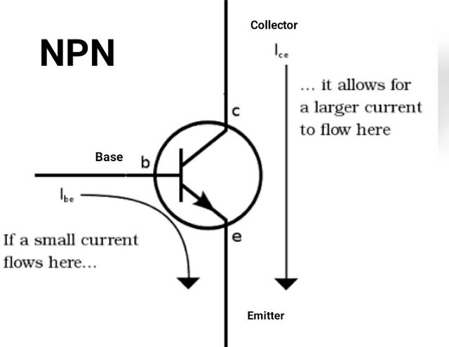
The NPN is made when a p-type semiconductor is sandwiched between two n-type semiconductor giving it the name NPN, that is P between N and N. The direction of current flow through an NPN is shown below.
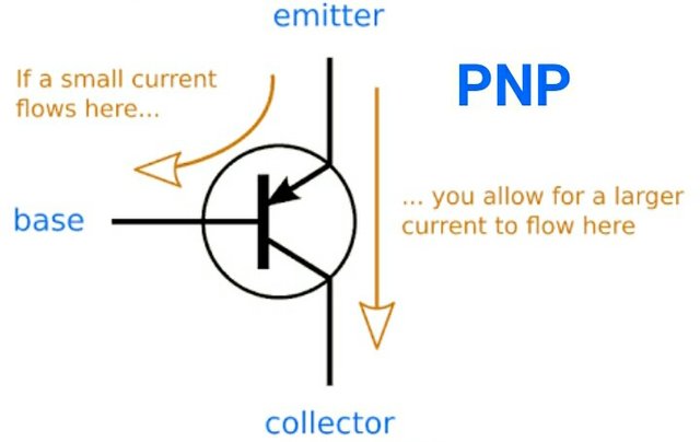
While, the PNP is made when an n-type semiconductor is sandwiched between two p-type semiconductor giving it the name PNP, that is N between P and P. The direction of current flow through a PNP is shown below
For the NPN current flows from the collector pin to the emitter pin, this is indicated by the arrow pointing out. Here the emitter pin is grounded and the collector pin is connected to the Vcc
While for the PNP current flows from the emitter pin to the collector, this is indicated by the arrow pointing in. Here the collector pin is grounded and the emitter pin is connected to the Vcc
We use the location of the arrow to differentiate the emitter from the collector. The emitter is always the pin with the arrow. The arrow is usually shared between the base and the emitter. Either pointing inwards or outwards.
How transistors really function
As mentioned earlier, a transistor can be used as a switch or as an amplifier. Let's get into it
TRANSISTOR AS A SWITCH
How does a transistor act as a switch?
To understand how a transistor function as a switch we will make use of the NPN transistor, so as to make things simpler. But do know that what can be done to an NPN transistor can also be done to a PNP transistor. They both work the same way but with some differences.
The base pin of the transistor is what determines if the transistor is actually 'ON' or 'OFF'. 'ON' in the sense that current flows through the transistor, that is from the collector to the emitter (NPN) and from the emitter to the collector (PNP)
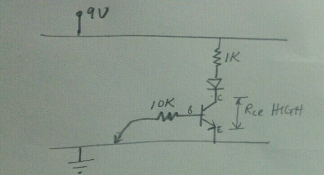
So, if the base is connected to Vcc (HIGH) the transistor will turn ON and current will flow. To further understand this, it is good that I point out that between the collector and and emitter a resistance exists, let's call the C-E resistance Rce. What really happens when the base is connected to a high is that the C-E resistance Rce drops too low, letting current flow from the collector to the emitter (NPN)
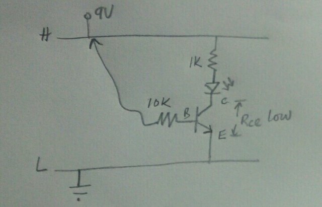
While when the base is connected to ground (LOW) the C-E resistance Rce builds up too high, kind of stopping current from flowing from the collector to the emitter. Remember the analogy between resistance and the flow of current
How can we apply this?
Knowing how the transistor behave we can put it to good use in our circuitry.
We could create a timer. How?
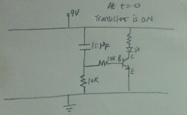
We first create a voltage divider using a capacitor and a 10K resistor, with our base terminal of the transistor we tap between the capacitor and resistor. Next we connect an LED and a resistor as shown below.
At the initial time the resistance of the capacitor is zero, thus the resistance of the capacitor is initially zero ohms and the potential across the 10K resistor is close to 9V (HIGH) meaning Vout (what the transistor sees) is high and the transistor comes ON, thus the LED turns ON.
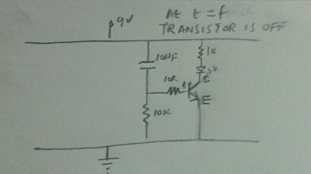
After some time when the capacitor is fully charged and the resistance across the capacitor is at maximum, the potential difference across the capacitor is greater and closer to 9V. Meanwhile the potential across the the resistor is smaller and close to 0V, meaning Vout (what the transistor sees) is Low and the LED turns OFF.
Transistors are so sensitive to current that's why we usually connect a resistor to a transistors base, so that it doesn't burn out. The value of the resistance is dependent on the transistor, for this reason, when picking out the right resistor we need to consult the datasheet
We can also create an inverter curcuit with transistor. How?
We connect two transistors as shown below. The first transistor (1) connected not much different from timer circuit. And it's base connected to a voltage divider made from a resistor and another transistor (2). Then the base of the transistor (2) to a jockey. Think of a jockey as an extension of the base.
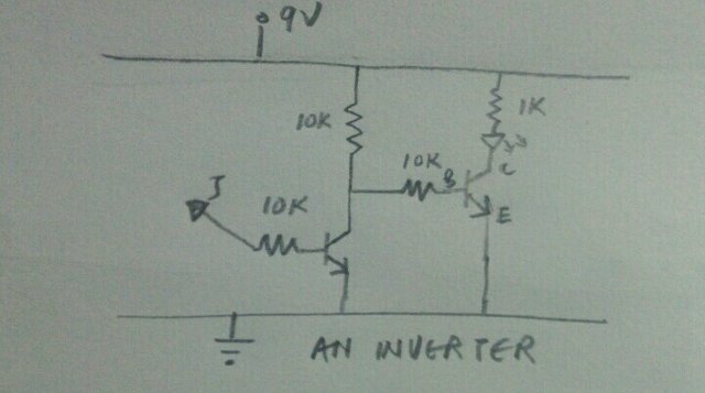
When we use the jockey to touch Vcc, the transistor (2) comes ON lowering its Rce resistance. Hence, the voltage (potential) across the transistor, Vout, which transistor (1) sees is LOW (closer to 0V) and the transistor (1) remains OFF, meaning the LED doesn't come ON WHY?
But when the jockey is used to touch Gnd the transistor (2) is OFF increasing its Rce resistance. Hence, the voltage (potential) across the transistor, Vout, which the transistor (1) sessions is HIGH (closer to 9V) and the transistor (1) comes ON, meaning the LED comes ON.
Therefore when the input at the transistor (1) is HIGH the output from transistor (2) is LOW and whenever the input to transistor (1) is LOW the output from TRANSISTOR (2) becomes HIGH
TRANSISTOR AS AN AMPLIFIER
As we have seen, by varying the input to the base, either HIGH or LOW we vary the output of the transistor, that is, the transistor either comes ON or OFF.
How about in between. What do I mean? I mean in between HIGH and LOW as input to the transistor. Making use of transistors as amplifiers involve playing with the input to the base of the transistor not completely OFF not completely ON. By doing so we play with with C-E resistance and also the output potential of the transistor.
Therefore with every little variation to the input potential of the transistor we get a large variation in the output potential of transistor. This is what amplification is all about.
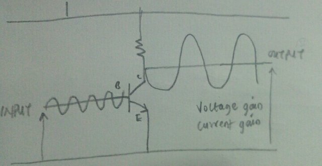
Something like the image above. Don't mind me. I know I need to improve on my drawing.
To Conclude
With the basic knowledge of how transistors work we could do many things. The application of transistors in the electronic world is not limited to those mentioned above.There is still so much more to transistors, it doesn't end in this one post. Explore the internet get to know more, and you would be amazed at what transistors could do.
Thanks for reading. Hope you enjoyed it. Until next time
Reference:
Image Credit:
- Image 1 from pixabay.com
- Image 2 and 3 from sparkfun.Com
- Other Images are mine

Excellent friend, how nice to know that behind all this technological application there is such a wonderful physics, and I am happy to study all that behavior, I love creating semiconductor compounds, but what fills me with happiness is when we find a compound that serves to many things especially the optoelectronic area
Wow. Down to making semiconductor compounds. Would like to know more
Merry Chriatmas!!! Wish you have a great one !!! :)))
Really nice content!! Upvoted and followed!!
I like your raw drawing really much!!
I am currently hosting a science picture contest with sbd and sp as award. Feel free to see if you are interested :D
https://steemit.com/sciencepic/@mcw/christmas-science-picture-challenge-1-with-sbd-and-sp-prize-1-sbd-sp
Thanks. I will check it out
Great!! Enjoy :D
Congratulations @kenadis! You have completed some achievement on Steemit and have been rewarded with new badge(s) :
Click on any badge to view your own Board of Honor on SteemitBoard.
For more information about SteemitBoard, click here
If you no longer want to receive notifications, reply to this comment with the word
STOP