The road to CCNA - Part 1 - OSI Model - Layer 1
The road to CCNA - Part 1 - OSI Model - Layer 1
Section 0 - About this
I'm not sure if this fits into Steemit, but I've decided to share some of the knowledge I have in computer networks.
I've worked as an educator/teacher within computer networking and science for 8 years now and have always wanted to share my understanding about computer networks in an easy-to-grip fashion. I'm certified in Cisco (CCNA, CCNP, CCDP, CCNA: Security) as well as a authorized train-the-trainer instructor, and ordinary student instructor within the Cisco Networking Academy.
One of the first things I tell my students when starting a new class is "My way of teaching is conceptual, not necessarily factual. So don't be afraid to correct me if I'm wrong". And by conceptual I mean "I'll teach you to understand it, not to know all the facts". That is atleast according to me, one of the most important aspects of a great network engineer. To know the concepts, to understand them and to be able to put facts into context.
Facts without context or ability to put them to use is worthless, and you cant utilize your knowledge without a good understanding of the concepts.
So, I will therefor try to put the same thinking into this little "Networking 101" I'm going to start here on Steemit. If you follow me, be prepared to get a few occasional strange analogies and some things that are outright wrong (but at the same time in the context could be seen as right).
So Part 1 (this part) will be about the OSI model more specifically Layer 1,. In my way of explaining it. This is a standard lecture I give several times per year and I'll try to condense the thinking into a text that won't be "TLDR".
My goal with the series will be that combined with some googling, browsing of wikipedia and a bit of laboration using available tools. You'll eventually reach the "CCNA" level. I'll give you the tools, the understanding and the base concepts, it's up to you to get the details and facts needed to complete the "profile".
Section 1.0 : The OSI Model
If you grab a book, any book, about networking you will be almost sure to find some reference to the OSI-model. Be it a passing mention in a sentence such as "This is a layer 3 switch" or a more in-depth explanation of it. There will always be some kind of trace of it.
So what is it? What is the OSI model and why is it important?
Well...It's a model, but historically it was more than that. In the late 70s and early 80s when the Internet had just begun it first few steps towards becoming the global network we all know and love today there weren't really any standard way of communicating between the big mainframes and computers of the day. IBM had it's own protocols and so did all the other large coorporations.
ISO, the International Standards Organisation, set forth to build a standard for communcation between systems from different manufacturers. The Open System Interconnection model, was the proposed solution. But when the OSI made it's big debut, the TCP/IP stack had more or less already become the de facto standard on the internet. And TCP/IP uses then same train of thought as the OSI-model, so they do work together. But the fact is, TCP/IP doesn't always completely fit inside the OSI models layered approach, which is why some of the layers can seem a bit awkward and hard to precisely explain what their role in the modern networks are. We'll just skip those layers while explaining the model.
Anyway, the model is composed of 7 different Layers, which each has their own specific task in the communication between computers or systems. See the picture below for reference:
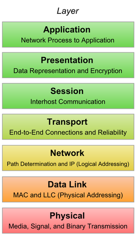
Each layer has it's set of corresponding protocols and technologies. We'll break them down one by one, but in this first part. Let's concentrate on Layer 1:
Section 1.1 - Physical Layer
This layer defines the physical media over which the communication is set to take place. Be it via radiowaves, laser/light, copper-wire or any other media. This is defined here.
If our media is "copper cables" or "fiber optics" the Layer 1 standards also define such things as cable characteristics (impedance, gauge, jackets, shielding, connectors) and so on. I won't explain this here, as there is soo many different connectors and cable types out there so just google "Network Connectors" or "Fiber optical connectors" or similar to get a list of the different connectors available.
The main responsibility of the Physical layer is to get a bunch of bits (bit = 1 or 0) safely from one side of the media to the other. It is not aware of, nor responsible for, anything else. This is the main and only responsibility of the physical layer.
But to be able to achieve this, it needs to have some tools, rules and a set of parameters to work within. This is what I'll explain first:
Section 1.1.1 - Signal Levels
Quite obviously if you want to have some sort of communication you need to have a signal. And if you have a signal you'll need to define a set of "levels" which are reasonable and won't hurt the receiver or get to weak on the way to the receiver.
Think about it this way, if you are in a room with another person standing next to you. How loud does he need to speak? Not that loud right? If he starts screaming at you, you'll have a hard time keeping up with what he's saying just because it is "too loud". Eventually, if he is superhuman or too close , he will break your eardrums.
So, a too strong signal isn't really effective. What about something too low? Well, using the analogy above you'll understand that that isn't what we are after either. We'll also need to take into account the other parties hearing (so called sensitivity) when deciding what the lowest possible signal level is.
We'll have to set some "middle ground" which will keep both parties happy.
Section 1.1.2 - Attenuation
To be able to find the middle ground, we'll need to cover attenuation as well:
The further a signal travels, the weaker it will become. Take the same room as above, place both communicating parties in each corner and make the room 10x larger. Will the same "force" or signal level still be enough to reach the other side? No, it wont. If you keep making the room larger at some point you'll reach a size where the other party does need to scream to reach you, and at a even larger size not even screaming will get the signal across. If you want to look at it in some of the weird ways I look at the world, the signal gets weaker due to friction. Compare this to your own strength. If you push a box full of heavy stuff across a large floor, you'll get more and more tired and it'll go slower and slower as you progress. Not a perfect analogy I know, but good enough for you to grasp the concepts.
Let's keep the box and floor analogy and we'll cover how frequencies affect attenuation:
Section 1.1.3 - Frequencies vs the world
Different frequencies have different attenuation, this is basically regardless of media: Higher frequencies always have higher attenuation!
If you've ever lived in an apartment you're likely to have had neighbors throwing a party.
What frequencies of their loud music do you hear at such a party? The bass, mid or high frequencies? Well, in most cases you here the bass and a little bit of the mid frequencies. The thicker the walls and the further the distance the more attenuated the higher frequencies becomes and the less of them you hear.
But why is this? Well, back to the "Box on the floor analogy".
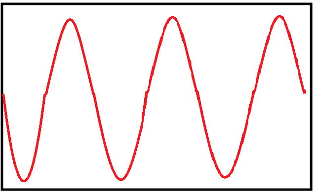
Higher frequencies have shorter wavelengths, the red line on the picture below is a high frequency with short wavelength: If the black box is the walls of a room and the red line is the path you are to push your box, you see that the total distance you push the box is further than just pushing it straight across.
Therefor more energy is lost on the way, and thus higher attenuation of the signal.
Compare this with a lower frequency with a longer wavelength (blue):
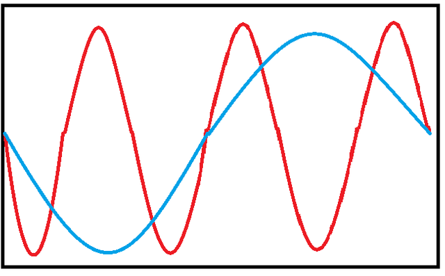
So, seeing this it's obvious which path I'd prefer to push that big ol' heavy box of ours.
But wait? Radiowaves or light doesn't travel on floors? Right, but there's always molecules and such in the air which will make the path a bit more bothersome for the higher frequencies (Green). The higher frequencies travel a "farther distance" from point A to point B so is more in risk of hitting some of those unwanted green dots.
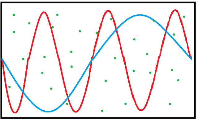
Light is pretty much the same, the sky is blue because the blue light (blue light has a higher frequency than red, contrary to the pictures above) meets an ugly molecule that is a bit larger than the lights wavelength so it basically just hits that molecule and gets reflected (easy, not so correct way of seeing it).
Section 1.1.4 - The middle ground
So we now know that the frequencies, signal levels and attenuation all go hand in hand. What we need to do now is to find a middle ground. In the Layer 1 standards this is done by simply combining a few factors: "How far do we need to reach", "How much power output is reasonable" and "What frequencies are available". Basically it all comes down to cost and sacrifice.
So, right now we have a signal that can reach from point A to B, but didn't I write that the main point of Layer 1 is to transfer Bits (1s and 0s) from point A to B? Yes, that is correct. But to do that we need to cover modulation.
Section 1.2 - Modulation
Modulation is the act of coding or decoding something into or from a signal. This can be done in numerous ways, but we'll take an easy example, to achieve CCNA you won't need to be a whiz in modulation, you'll be fine just knowing what it is used for.
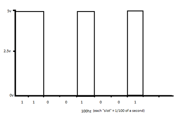
Let's play with the thought that we have this super easy L1 standard, which states that our acceptable transmission signal level is 0-5 volts and everything higher than 2.5v is seen as a 1 and everything lower than 2.5v is a 0. This standard also defines that the frequency or rate of change in a transmission is 100hz.
So, if our signal changes 100 times per second, 5v is the ceiling signal level and we want to transfer the byte (one byte is 8 bits) 11001001 this would look something like:
If you had to keep the 5v max signal level, and the 100hz frequency. How would you go about increasing the transfer rate from 100bits/second as it is right now, to say 200bits/second?
Remember, the top signal level and the frequency is set and cannot be changed.
(SPOILER: Possible answer below, scroll down when you think you've got a solution or have given up):
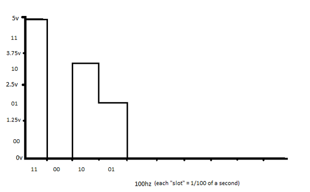
One of the possible answers, while keeping the 100hz and the 5v max signal level, is to increase the number of levels. from 2 (0-2.5v = 0, 2.5v-5v = 1) to 4. Now we can transfer the same string of 1s and 0s at half the time. Thus doubling our possible bitrate.
This is an example of an extremely simple sort of modulation. And really is all you need to know to pass the CCNA in a "modulation" viewpoint.
If you want to do some research yourself, two simple modulation methods are AM and FM, which are used almost every day by most people when listening to an ordinary old radio. Google them and from there you can work your way to more complex modulations!
Ok, this concludes the Layer 1 part, this is really all the concepts you need to know on that topic. Some base facts you do need to know are the types of connectors on the cables, the difference between different types of TP cable and some other parts. Wikipedia has an excellent article on that subject: https://en.wikipedia.org/wiki/Modular_connector#8P8C
I'll follow up with Part 2 in a few days, where I'll cover Layer 2 and more specifically Ethernet.
I'm guessing the whole "CCNA Series" will take at least a couple of months, but then again, you'll get time to dive into the subject yourself between parts :)
Please upvote and reply if you like what you've read and would like to see more of this series in the future.
I get it...woohooo! :)
Congratulations @johanbogg! You have received a personal award!
Click on the badge to view your own Board of Honor on SteemitBoard.
For more information about this award, click here
Congratulations @johanbogg! You have received a personal award!
Click on the badge to view your Board of Honor.
Do not miss the last post from @steemitboard:
Congratulations @johanbogg! You received a personal award!
You can view your badges on your Steem Board and compare to others on the Steem Ranking
Do not miss the last post from @steemitboard:
Vote for @Steemitboard as a witness to get one more award and increased upvotes!