Logic Design - VHDL Finite-State Machines

Hi, its me again! Today we will talk about Flying Spaghetti Monsters...just joking. We will talk about Finite-State Machines or FSM's for short! It would be a great idea to check the Sequential Circuits in VHDL first if you haven't already! I will this time just talk about the differences when writing a mealy and a moore FSM and also implement some Example Diagrams and simulate them in Modelsim. So, without further do let's get straight into it!
Quick Recap:
A Sequential Circuit works as a Finite-State Machine mostly. We start from a specific State and depending on the Previous State and the Input we then go to the Next State! This transition happens only during a specific clock event. For us this clock event will be a Edge from '0' to '1' and so all our FMS's will contain DFF (that we will not actually see) that will be Positive Edge-Triggered. So, such an FSM contains Memory Elements and Combinational Logic to connect those together with the Inputs and Outputs.
FMS Types:
We have 2 types of FMM's. A Mealy and a Moore FSM differentiate in the way we get the Output! A Mealy Output depends on the whole transition and so Previous State and Input. A Moore in the other hand has a specific Output depending on the State we currently are in and so the Output is binded together with the Current State.
You might remember how we can separate them when getting a Diagram, but because I will use this concept in all our Examples I rewind your memory really quick. A Mealy FSM Diagram will contain the Input/Output value in each Arrow-Transition and the States will just have the number/name that separates them from the others. A Moore on the other hand will have only the Input on the Arrow and the Output will be inside of the State.
This looks like this (picture from Sequential Circuits Theory):
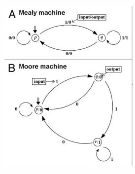
We will have such Diagrams in our Example Section!
Implementing FSM's in VHDL:
The basic structure of Coding a Sequential Circuit stays the same. A Code for such a Sequential Circuit needs to have a Clock and a Reset in the Input and 1 or 2 processes inside of the architecture that only change the state (and output when mealy) when a positive edge event is triggered. To get from one state to another we will use a lot of if and when statements that check the input value and Previous State. The output can be found directly from the Transition and so in the same process when we have a Mealy machine, but when having a Moore we will need a separate process for that. Sometimes we can get to a specific State starting off from different States that can make our Code smaller when having a Moore FMS for example. Some States may also be Starting States or Final States and so we can either don't return to them or can't get away from them.
The States will be defined as new Datatypes! We can do it pretty simple by using this line of code:
type state_type is (s0, ..., sn);
After that we define a signal of type state_type like that:
signal state: state_type;
So, our Code Layout looks like this:
-- define entity entity_nameentity entity_name isport( clk: in std_logic; reset: in std_logic; -- inputs -- outputs);end A;-- define architecturearchitecture arch of entity_name is -- define state type type state_type is (s0, ..., sn) signal state: state_type begin -- process for state switching process(clk, reset) begin -- asynchronous if to reset fsm -- if/when statements for each transition -- if mealy we also set the output end process; -- process for output if moore process(state) begin -- if/when statement for each state/output combination end process;end arch;Hope that you can see that it's actually not quite difficult to write a FSM. Knowing how a Mealy and Moore differentiate can save you a lot of time, cause the coding process is actually always the same. Only the States, Transitions and Outputs will change. The rest stays mostly the same!
So, let's now get into 1 example for each FSM Type!
Example Section:
Example1:
We will first implement a Mealy FSM! The Diagram looks like this:
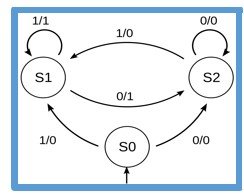
Because else we would end up with a lot of statements we will use a second process for the output, cause if you check out the Diagram you will see that the Output depends on the previous State only that can make our Code smaller then when having a output assignment in each Transition(Previous State + Input)!
So, our Code looks like this:
library ieee;use ieee.std_logic_1164.all;entity A isport( clk: in std_logic; input: in std_logic; areset: in std_logic; output: out std_logic);end A;
architecture arch of A is type state_type is (s0, s1, s2); signal state: state_type; begin process(clk, areset) begin if areset='1' then state<=s0; elsif(clk'event and clk='1') then case state is when s0=> if input='1' then state<=s1; else state<=s2; end if; when s1=> if input='0' then state<=s2; end if; when s2=> if input='1' then state<=s1; end if; end case; end if; end process;
process(state) begin case state is when s0=> output<='0'; when s1=> output<='1'; when s2=> output<='0'; end case; end process;end arch;Running it in Modelsim and assigning the Clock value using right-click we get the following results:
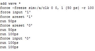

You can see that it actually can get a lot of fun running a FSM in Modelsim, cause you can jump from one state to another much easier by simply running the Circuit Simulation after assigning the correct input value!
Example 2:
Let's now implement also a Moore Diagram that looks like this:
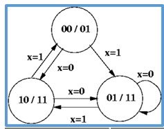
This time we will also define constants for the outputs! I will also make the State_type we define ourselfes be a subtype of std_logic_vector! You will see that this time we have to make the Output assignment in a separate process anyway, cause it doesn't work else.
So, our Code looks like this:
library ieee;use ieee.std_logic_1164.all;entity B isport( clk: in std_logic; input: in std_logic; areset: in std_logic; output: out std_logic_vector(1 downto 0));end B;
architecture arch of B is subtype state_type is std_logic_vector(1 downto 0); signal state: state_type;
constant s0: state_type:="00"; constant s1: state_type:="01"; constant s2: state_type:="10";
begin
process(clk, areset) begin if areset='1' then state<=s0; elsif(clk'event and clk='1') then case state is when s0=> if input='1' then state<=s1; else state<=s2; end if; when s1=> if input='1' then state<=s2; end if; when s2=> if input='0' then state<=s1; else state<=s0; end if; when others=> end case; end if; end process;
process(state) begin case state is when s0=> output<="01"; when s1=> output<="11"; when s2=> output<="11"; when others=> end case; end process;end arch;The simulation in Modelsim looks as following:
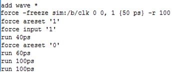

You can see that it was a little more complicated that way, but the whole logic behind writing the Code stays the same! Also, yes I had all that already finished up inside of a word document :)
And this is actually it! Hope you enjoyed this post!
From now in VHDL we will implement Computer Components like ALU's, RAM and also simulate more advanced FSM's! So, VHDL gets now into the Assembly-Like phase also :D
Until next time...Bye!