Logic Design - Sequential (Synchronous) Circuits

Hi, its me again. This time in Logic Design we will talk about Sequential Circuits! We will use everything we talked about in the previous 2 posts about Clocks and Flip Flops and combine those together with the previous Combinational Logic (everything before Clocks was actually Combinational Logic) to form Sequential (Synchronous) Circuits! We will talk about State Tables, Equations and Diagrams that are used in those new Circuits and I will show you an full example at the end. So, let's get started!
State Tables:
In Sequential Circuits the Output not only depends on the current Input, but also on the previous State the Circuit was in. So, we will have another form of Truth Table called State Table, that shows us how we go from an state with a specific Input to another.
Remember this stuff:
- States may not be accesible from all States and so we might need to go in other states in between.
- Some other states may be final states and so we can't go to another state anymore.
- Lastly there are some states that are entry states and we can't get to them anymore after leaving them!
So, you should know now that not all States are connected with each other!
A State Table can look like this:
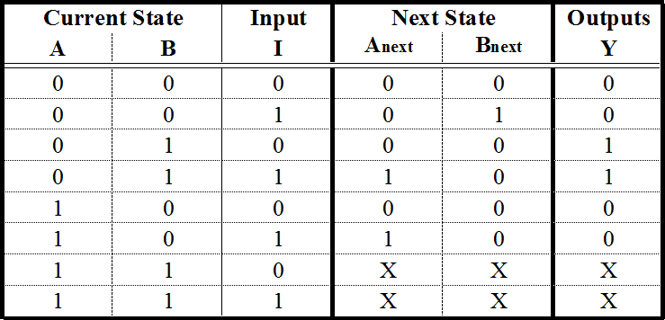
So, we have the Current State and Input on the left, and the Next State and Output on the right. If you remember from Flip Flops we said that the Outputs only changes when we have a specific clock event occur. It's exactly like that here! So, all this State Switching happens only when a clock event occurs while the Current States and Input have the specific value to get us to the Next State and give us the Output shown. So, all the other time the State gets stored and doesn't change.
If we think about the Output we can see that sometimes we go into the same State from another State and the Output is different. That means that the Outputs depends on the Transition and not the State! This kind of a Circuit is called a Mealy State Machine! If the Outputs depends on the State and not the Transition than we have a Moore State Machine! Both are Finite State Machines (FSM) and you will understand those things better when we get into Diagrams in this post, and even more when we get into VHDL Coding some posts later on!
So, to make a recap. A State Table is the equivalent of an Truth Table for FSM's or Sequential Circuits. States are not always connected to each other and we have States that are entry or final States. The Output depends either on Input and State (Transition) or the State only. Those two Types of FSM's are called Mealy (Transition) and Moore (State) State Machines.
State Equations:
Using the State Table we can create the Sequential Circuit needed doing stuff we already know how to do! This time we not only have a Equation for the Output, but we will also need Equations for each State. That means that the things in the Circuit that define a State (like A,B on the State Table we had previously) will need a Equation too, that mostly contains themselves! (you will see what I mean in a minute)
For example the Equations could be:
A(t+1) = x’y + xA
B(t+1) = x’B + xA
z=B
As you can see now, we will have a Circuit for each of those Equations. The first two are for the State Switching and the last is for the Output. This time the Output depends only on the State and we have a Moore FSM. This Switching will occur only on an specific Clock Event and the easiest way to do this is using D Flip Flops, cause as you remember a D Flip Flop puts the Input's value to the Output everytime a clock event occurs!
We will not always have the Equations directly and getting them from a State Table is pretty easy. Remember Karnaugh Map? Yeah, sometimes it's needed, but the State Table we have on top is even easier to do, using minterms directly and then doing Boolean Algebra on them.
So we have:
A(t+1) = A'BI + AB'I = I(A'B + AB') = I(A ⊕ B)
B(t+1) = A'B'I
Y = A'BI' + A'BI = A'B
We will create a simple Circuit that uses the Equations we had previously and not now at the end of the post, where I will have a full on example!
State Diagrams:
State Diagrams are another way of representing FSM's. In this Diagram each Circle represents a State and the Arrows represent transitions from one State to another. Here you can then see more clearly how Mealy and Moore FSM's are different. In Mealy Machines each Arrow shows the Input to go to the State and the Output we will have, but in Moore the Arrow only shows the Inputs and the Output is defined inside of the State!

From this Diagrams we can easily create a State Table and after that an Equation, but I will get more into that later on in VHDL, where I have many Examples for you!
Example:
Let's take the Equations I showed you previously!
A(t+1) = x’y + xA
B(t+1) = x’B + xA
z=B
We have 2 Variables that are called A and B that define a State, cause we have a Previous (A, B) and Next State (t+1) of them! We also have 2 other Inputs called x and y, but those are normal Inputs and don't have next or previous States! We will fill a State Table that contains all the different Combinations of States and Transitions, by putting the 3 (in each of those we have only 3) Input vales inside of those Equations!
We end up with this State Table:

We don't needed to do this, but it's much easier to create a Diagram that way!
We have 4 States (Circles) where A,B have the values 00, 01, 10, 11 and we will have Arrows for each different Input Transition, cause we have a Moore FSM because as you can see the Outputs for the same States are the same (00 and 10 have 0 and 01 and 11 have 1)! The two different Inputs will be put together like 00, 01 etc. and the Output will be put inside of the State as 00/0 for example.
So, the State Diagram looks like this:

As you can see I don't put some Inputs, but only those that are important!
To create the Logical Circuit we will put a D Flip Flop for each of the 2 State Variable A and B and a Clock. The rest of the Circuit will be created as the State Equations showed us.
So, the Circuit will look like this:

This is the end of this post! Hope you enjoyed it!
This was actually the last important post before getting into MultiSim! So, get ready for MultiSim Implemenation! I also have some Logic Design Theory stuff more that I will put in between of MultiSim and we will get into VHDL Coding after MultiSim!
Until next time...Bye!
Nearly everything you do is of no importance, but it is important that you do it.
- Mahatma Gandhi
Cool post. Just curious, is VHDL still used in real life circuit design projects?
It's a good language for Circuit Designing.
As I learned in University a Chip is designed first as a Schema, then gets coded in an HDL (Hardware Descripting Language) that can be VHDL or Verilog and lastly we have optimizations.
So, yes it is possible that many use VHDL for Circuit designing.
I will show off VHDL, cause Verilog is too C-Like for my taste. :)
Great. I have done VHDL as well as a second year student a looong time ago :) . It is funny that I forgot most of the concepts regarding sequential circuits. The post is a good refresher.