Arduino project : KY-039 and LCD to monitor pulse rate
What Will I Learn?
In this tutorial, you will learn the following

- how to connect (16X2) LCD with IIC breakout with arduino
- how to program a code on arduino Desktop IDE
- how to connect all the components connection using diagram
- how was the heartbeat module works on arduino, we will learn to built an Arduino based heartbeat monitor which counts the number of heartbeats in a minute. Here we have used a heartbeat sensor module which senses the heartbeat upon putting a finger on the sensor.
Requirements
- Step 1: Gather all the Requirements
For this part, you will need the following arduino components

Difficulty
- Intermediate
Tutorial Contents
- Step 2: Experimental Procedures
Arduino UNO R3 microconroller

The uno R3 is a microcontroller board based on the ATmega328P (datasheet). It has 14 digital input/output pins (of which 6 can be used as PWM outputs), 6 analog inputs, a 16 MHz quartz crystal, a USB connection, a power jack, an ICSP header and a reset button. It contains everything needed to support the microcontroller; simply connect it to a computer with a USB cable or power it with a AC-to-DC adapter or battery to get started. reference
The connection of KY-039 to arduino
In this project we will be using Heart beat sensor module to detect Heart Beat. This sensor module contains an IR pair like an ordinary led which actually detect heart beat from blood. Heart pumps the blood in body which is called heart beat, when it happens the blood cons in body changes. And we use this change to make a voltage or pulse electrically
Heart beat sensor module’s output pin is directly connected to analog pin 0 of arduino. Vcc and GND are connected to Vcc and GND.

- Sensor pin - AO
- GND - GND
- VCC - 5V
The connection of 16x2 LCD with i2c breakout to Arduino
LCD has 4 pins (1) VCC it refers to the power signal of the LCD typically connected to 5volts, (2)GND or sometimes zero voltage, It is also the common connection of the LCD must connect to in one way or another path in order to complete the circuit. the SDA and SCL refers to the 16 normal pins of the LCD which connected to analog pin outputs of the arduino
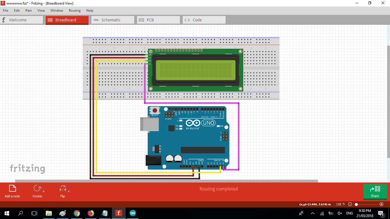
- GND - GND
- VCC - 5V
- SCL- A4
- SDA - A5
DIAGRAM
- Step 3: Connect all components in one circuit breadboard/PCB

SOFTWARE
- Step 4: Download the Software and Libraries
We are done building the circuit so lets start to set up and make a code for this. we are going to use the arduino ide, to set the sketch for this, if you dont have make sure to download the Arduino IDE for your specific operating system. I’ll leave a link to where you can download this software: https://www.arduino.cc/en/Main/Software

After the installation of the IDE We need to download the i2c library To get the i2c 2x16 LCD library for the Display download it here: https://github.com/arduino-libraries/LiquidCrystal
- Step 5: Include library to Arduino IDE
When the zipfile is already downloaded open the file then copy the folder unzip the folder to your desktop you can rename it as liquidcrystali2c
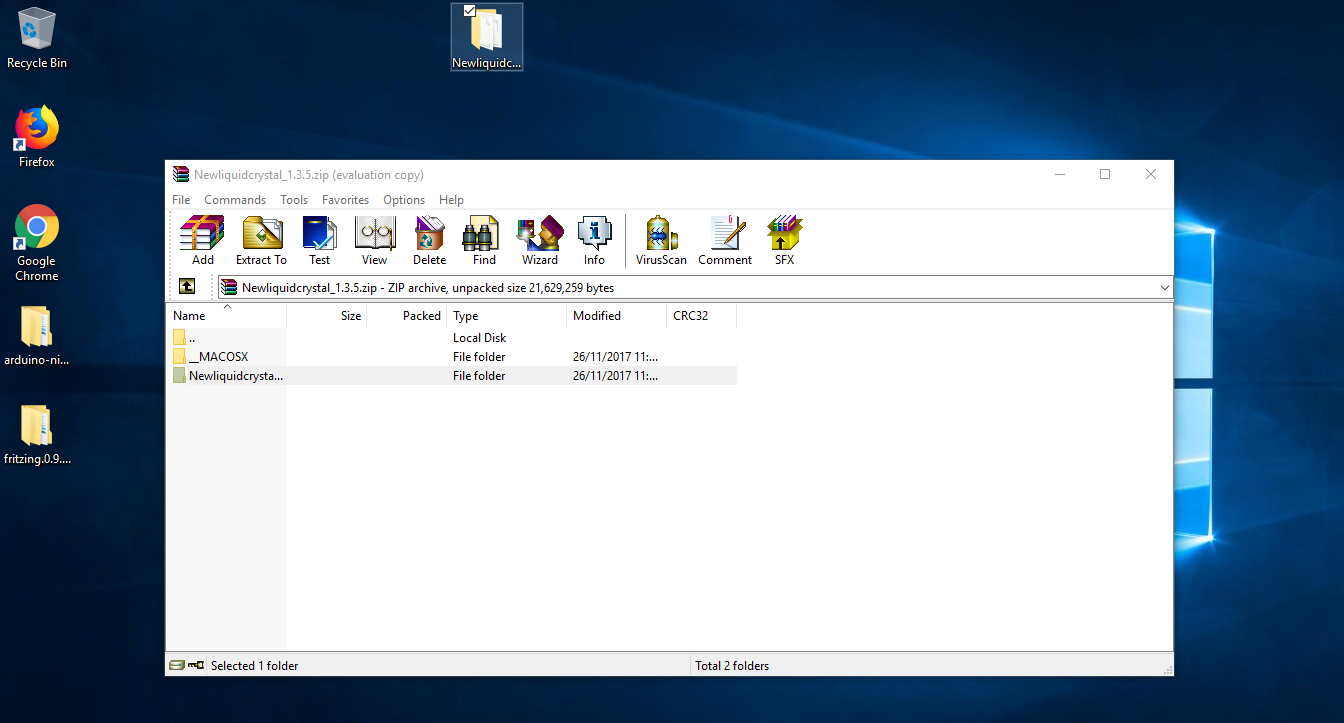
Cut the lcd folder in your desktop then go to your folders then locate the arduino folder>> libraries then paste it there. and now the folder liquidcrystal library is already in the arduino ide libraries.

Programming
- Step 6: Build the code
In the code we have used analog read function to read output of Heart Beat sensor module which is connected to a0 of the arduino, when making a code we need include all the libraries we will be using we have to add the library that we have recently downloaded. #include <LiquidCrystal_I2C.h> for the i2c 2x16 LCD DISPLAY. and the #include <Wire.h> which is already in the IDE.
The address LiquidCrystal_I2C lcd(0x27, 2, 1, 0, 4, 5, 6, 7, 3, POSITIVE); is the i2c address woth only 4 pins, if your using the 16 pin then you need to use different address here.
setup() method is ran once at the just after the Arduino is powered up and the loop() method is ran continuously afterwards.
setup() is where you want to do any initialisation steps, and in loop() you want to run the code you want to run over and over again.
pinMode(A0,INPUT); Define the sensor pin of hearbeat sensor is connected to the analog pin A0 on the arduino board.
lcd.print(" Heart Monitor "); the iput text word that appears on the serial monitor or lcd display.
delay(); 1000 is equals to 1 second timeframe.
SOURCE CODE
#include  <Wire.h> // include wire
#include <LiquidCrystal_I2C.h> // include liquidcrystal i2c libary
LiquidCrystal_I2C lcd(0x27, 2, 1, 0, 4, 5, 6, 7, 3, POSITIVE); // 16x2 LCD address 0x27
   double alpha=0.75;
   int period=20;
   double refresh=0.0;
void setup(void)
{
   pinMode(A0,INPUT);
   lcd.begin(16,2); // define LCD 16 columns and 2 rows
   lcd.clear();
   lcd.setCursor(0,0);
}
void loop(void)
{
   static double oldValue=0;
   static double oldrefresh=0;
   int beat=analogRead(A0);  //define sensor pin to AO
   double value=alpha*oldValue+(0-alpha)*beat;
   refresh=value-oldValue;
   lcd.setCursor(0,0); //we start writing from the first row first column
   lcd.print(" Heart Monitor "); // text to be displayed on the LCD when boot up
   lcd.setCursor(0,1);
   lcd.print("          ");
   lcd.setCursor(0,1);
   lcd.print(beat/10);
   oldValue=value;
   oldrefresh=refresh;
   delay(period*10);
}- Step 7: connect the arduino microcontroller to your computer via usb cable.
your computer will automatically scan the device driver, to verify the board of the arduino, on the IDE click >. TOOLS then verify the board type and PORT where the USB is connected.

- Step 8: Copy the source code to arduino IDE sketch bar. click the UPLOAD icon on the upper right side toggle, it will automatically compile the sketch to check if theres an error with the code before uploading to the arduino board.

- Step 9: DONE uploading. Test, once the code is succesfully uploaded test the sensor if its working and able to detect your current heart rate index.

Previous Arduino Projects
Arduino Based SUPER MARIO game using tobiaso marduino library
OLED display Gauge Meter using Potentiometer - arduino
7-Segment counter 0-9 with push buttons up and down
Soil Moisture Sensor with a Nokia 5110 LCD display Arduino Project
Posted on Utopian.io - Rewarding Open Source Contributors
Your contribution cannot be approved because it does not follow the Utopian Rules.
Violated Rule(s):
My Opinion(s):
You can contact us on Discord.
[utopian-moderator]
Hello, as a member of @steemdunk you have received a free courtesy boost! Steemdunk is an automated curation platform that is easy to use and built for the community. Join us at https://steemdunk.xyz
Upvote this comment to support the bot and increase your future rewards!
Congratulations @pakganern! You have completed some achievement on Steemit and have been rewarded with new badge(s) :
Click on any badge to view your own Board of Honor on SteemitBoard.
For more information about SteemitBoard, click here
If you no longer want to receive notifications, reply to this comment with the word
STOPDo not miss the last announcement from @steemitboard!