Blinkit v2.2: Arduino integration | RGB mode
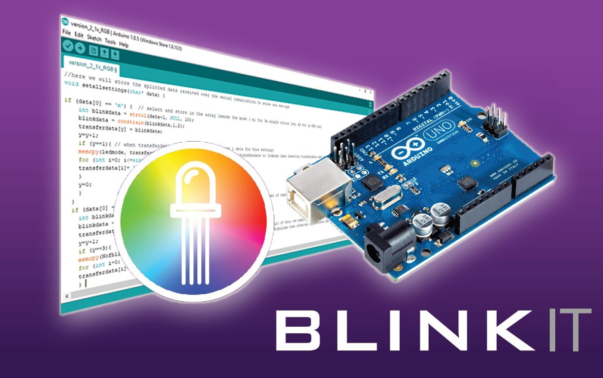
After the initial integration of Arduino to Blinkit project with the first mode (3 Single Colours LED), the second integration of Arduino to the fantastic Blinkit project is here. This to provide added versatility and an added feature to give the possibility to many DIYers and other Hobbyists that have an Arduino board to interact with Steemit and receive notifications such as new upvotes and new followers, etc...
What is Blinkit?
Blinkit is a notification software that can be used to give to regular and widely available devices a Steem purpose.

Supported devices:
- USB Sticks (with read/write status light)
- Philips hue lamps
- Sonoff smart Wifi switches
- Arduino Boards or compatible (Genuino, etc...)
Blinkit can look for new Steem account Upvotes and Followers, and it can notify on new Posts made by a user.
More devices will be added in the near future.
Blinkit is free and open source, and can be downloaded from the Blinkit Github page:
https://github.com/techtek/Blinkit
For more information about the new version of Blinkit please visit the following link

COMPATIBILITY
Current release has been tested only on an Arduino UNO board. Other boards like Mega and Nano should be supported (for Nano different PWM pins should be selected, for Mega nothing to change) but have not been tested yet. Users interested in using this new feature with other boards could submit a test contribution and let us know the result of their test.
New Features:
- Blink One 5mm RGB LED connected to an Arduino on new Upvotes followers and posts.
- Set the colour, the number of blinks and the blink delay for each notification (upvote, follower, post)
- Adjusted Console feedback from Arduino to test currently stored settings over Serial
Blinkit has been created by @techtek to give the possibility for every person to receive notifications about Steem activities such as new upvotes, new followers, new posts of a user, through the use of common and widely available devices. In the DIY caterogy one of the most known devices used is Arduino, a highly versatile programmable logic controller. This is why I thought of implementing a lot of features using Arduino boards in Blinkit.
Behind this second release is the desire to give more and more possibilities of interaction with Blinkit using Arduino boards. In fact now it is possible to have funny and colourful notifications of Steem activities.
Hereafter i will explain the wiring diagram and the code I developed for Arduino and will just show generally how is the interaction with Blinkit software taking place. Full details about Blinkit code for interacting with Arduino can be found in @techtek new post here.

Technology Stack
As the device in question is Arduino this involves the use of C/C++ languages/sub-languages.
Some basic electronics knowledge regarding LED pinout is required. For that purpous I will be posting soon a tutorial on how to determine the pinout of an RGB led and what are the resistors to be used with an Arduino board to keep your LED safe and the Arduino output pins safe.
How is it implemented?
The code is still devided in 6 parts like the single mode (more details regarding the first mode through this link) option:
- Declare/set the variables, the arrays etc
- Initializing the setups (Serial Comunication and Output pins)
- Receive serial data to be processed
- Receive serial data and split it in tokens declaring the functions that will handle such data
- Read splitted data and based on some marker store them in the right setting array
- Wait for triggers (upvote, follower, post) over serial and activate the led
1) Declare/set the variables, the arrays etc...
char buffer[22];

int RedPIN = 3; //pin for led 1 (single colour led) or pin for the Red led in the RGB led
int GreenPIN = 5; //pin for led 2 (single colour led) or pin for the Green led in the RGB led
int BluePIN = 6 ; //pin for led 3 (single colour led) or pin for the Blue led in the RGB led
//above pins must be DIGITAL PWM PINS (in Arduino Uno, PIN 3, 5, 6, 9, 10, 11 are PWM) in order to obtain the colours shades with the RGB led
int y=0;
int transferdata[3]; //array to be used to store the incoming settings and transfer them to the right setting array
int ledmode[2]; //this array will store the information regarding the ledmode (mode 1 for 3x single colour leds and mode 2 for 1x RGB led )
int blinkdelay[3]; //this array will store the information to be used for the blink speed (in this case it is a delay between blinks)
int Nofblinks[3]; //this array will store the information to be used for the number of triggers/blinks to do (number of repeated triggers)
int BRIGHTU[3]; // This array will store the information regarding the brightness of the RGB led for the upvote trigger (3 values, 1 for for each colour to create the blend with the others)
int BRIGHTF[3];// This array will store the information regarding the brightness of the RGB led for the follower trigger (3 values, 1 for for each colour to create the blend with the others)
int BRIGHTP[3]; // This array will store the information regarding the brightness of the RGB led for the post trigger (3 values, 1 for for each colour to create the blend with the others)
Compared to the Single led mode, what is new in this code are the new arrays BRIGHTU, BRIGHTF and BRIGHTP which will be storing the RGB value of the chosen colour for each notification BRIGHTU for upvotes, BRIGHTF for followers and BRIGHTP for post.
ledmode[], which previously accepted only value "1" for Single colour led mode now accepts also "2" which has been assigned to the RGB mode.
The rest of the variables and arrays have remained the same and have maintained the same function of handling the data received over serial.
2) Initializing the setups (Serial Comunication and Output pins)
void setup()
{
Serial.begin(9600);
Serial.flush();
    pinMode(RedPIN, OUTPUT); //set the selected pins as output
    pinMode(GreenPIN, OUTPUT);
    pinMode(BluePIN, OUTPUT);
}
In this setup I have initialized the serial comunication at a set baudrate (14400) and have set the previously defined pins as output pins. If you want to use a different baudrate just change the value in the sketch to any supported baudrate and don't forget to change the baudrate set for your board accordingly in the device manager (the tutorial for that can be seen through this link along with the tutorial on how to install the driver for Arduino Chinese Clones using CH340 marked chip)
What has changed here compared to the previous version is the name assigned to the variable containing the pin number we used as output which now has been named RedPIN, GreenPIN and BluePIN.
3) Receive serial data to be processed
void loop() //collecting the incoming data and filling the buffer with it
{
if (Serial.available() > 0) {
int index=0;
delay(100); // let the buffer fill up
int numChar = Serial.available();
if (numChar>22) {
numChar=22;
}
while (numChar--) {
buffer[index++] = Serial.read();
}
splitdata(buffer);
}
}
In this loop Arduino will listen to the COM port and wait for new data and once new data is detected it will fill the buffer and then redirects the data entered to the next function splitdata(buffer) that will split the that data in order to be processed later in the code. A small adaptation had been made in order to reduce the buffer size from 30 to 22 to get a little back little more free memory(removing some allocated memory to the buffer).
4) Receive serial data and split it in tokens declaring the functions that will handle such data
void splitString(char* data) { //splitting the data received based on a fixed separator (in this case the blank space " ")
//Serial.print("Data entered: ");
//Serial.println(data); // display data entered/received
char* info;
info = strtok (data, " "); //using strtok split in tokens the data entered in a sequences of contiguous characters separated by the delimiter " " (empty space)
while (info != NULL) {
setallsettings(info);
setLEDon(info);
info = strtok (NULL, " ");
}
// Clear the text and serial buffers
for (int x=0; x<21; x++) {
buffer[x]='\0';
}
Serial.flush();
}
Hereafter is the main structure of strtok:
char * strtok ( char * str, const char * delimiters );
Once data (str) has been received and once the buffer transfers the data to splitdata(), using strtok we split the data entered in tokens, a sequences of contiguous characters separated by a delimiter (const char * delimiters). In our case we have chosen the delimiter to be an empty space " ".
5) Read splitted data and based on some marker store them in the right setting array
//here we will store the splitted data received over the serial comunication to store our set-ups
void setallsettings(char* data) {

if (data[0] == 'm') {  // select and store in the array lemode the mode ( m1 for 3x single colour led, m2 for 1x RGB led)
    int blinkdata = strtol(data+1, NULL, 10);
    blinkdata = constrain(blinkdata,1,2);
    transferdata[y] = blinkdata;
    y=y+1;
    if (y==1){ // when transferdata is full of data (we expect 1 data for this setting)
    memcpy(ledmode, transferdata, sizeof(transferdata)); //copying transferdata to ledmode then clearing transferdata and resetting y,
    for (int i=0; i<=sizeof(transferdata); i++){
    transferdata[i]= '\0';
    }
    y=0;
    }
  }
  if (data[0] == 'n') { //store in an array called Nofblinks the sequence of the number of repeated trigger we want for each led and on which later leds will trigger
    int blinkdata = strtol(data+1, NULL, 10);
    blinkdata = constrain(blinkdata,1,30);
    transferdata[y] = blinkdata;
    y=y+1;
    if (y==3){                                                // when transferdata is full of data (we expect 3 values)
    memcpy(Nofblinks, transferdata, sizeof(transferdata));   //copying transferdata to Nofblinks then clearing transferdata and resetting y,
    for (int i=0; i<=sizeof(transferdata); i++){
    transferdata[i]= '\0';
    }
    y=0;
    }
  }
  if (data[0] == 'd') { //store in an array called blinkdelay the sequence of delays for each trigger
    int blinkdata = strtol(data+1, NULL, 10);
    blinkdata = constrain(blinkdata,1,1000);
    transferdata[y] = blinkdata;
    y=y+1;
    if (y==3){                                                // when transferdata is full of data (we expect 3 values)
    memcpy(blinkdelay, transferdata, sizeof(transferdata));   //copying transferdata to blinkdelay then clearing transferdata and resetting y,
    for (int i=0; i<=sizeof(transferdata); i++){
    transferdata[i]= '\0';
    }
    y=0;
    }
  }
if (data[0] == 'U') {
    int blinkdata = strtol(data+1, NULL, 10);
    blinkdata = constrain(blinkdata,0,255);
    transferdata[y] = blinkdata;
    y=y+1;
    if (y==3){                                                // when transferdata is full of data (we expect 3 values)
    memcpy(BRIGHTU, transferdata, sizeof(transferdata));   //copying transferdata to BRIGHTU then clearing transferdata and resetting y,
    transferdata[0]= '\0';
    y=0;
    }
  }
if (data[0] == 'F') {
    int blinkdata = strtol(data+1, NULL, 10);
    blinkdata = constrain(blinkdata,0,255);
    transferdata[y] = blinkdata;
    y=y+1;
    if (y==3){                                                // when transferdata is full of data (we expect 3 values)
    memcpy(BRIGHTF, transferdata, sizeof(transferdata));   //copying transferdata to BRIGHTF then clearing transferdata and resetting y,
    transferdata[0]= '\0';
    y=0;
    }
  }
if (data[0] == 'P') {
    int blinkdata = strtol(data+1, NULL, 10);
    blinkdata = constrain(blinkdata,0,255);
    transferdata[y] = blinkdata;
    y=y+1;
    if (y==3){                                                // when transferdata is full of data (we expect 3 values)
    memcpy(BRIGHTP, transferdata, sizeof(transferdata));   //copying transferdata to BRIGHTP then clearing transferdata and resetting y,
    transferdata[0]= '\0';
    y=0;
    }
  }
if (data[0] == '?'){   //send command set to view on serial all the current setups
  Serial.println("Current Settings: ");
  Serial.println("---------------------------------------------------- ");
  Serial.println(" ");
if(ledmode[0]== 1){
        Serial.println("ledmode is set to: 3x single colour LED ");
        Serial.println(" ");
  for (int i=0;i<=2;i++){
      Serial.print("Nofblinks for led");
      Serial.print(i+1);
      Serial.print(" is:");
      Serial.print(Nofblinks[i]);
      Serial.println(" Blinks");
    if (i==2){
      Serial.println(" ");
      }
   }
  for (int i=0;i<=2;i++){
        Serial.print("blinkdelay for led ");
        Serial.print(i+1);
        Serial.print(" is:");
        Serial.print(blinkdelay[i]);
        Serial.println(" Millis");
     if (i==2){
        Serial.println(" ");
        }
   }
}
   if(ledmode[0]==2){
              Serial.println("ledmode is set to: 1x RGB LED ");
              Serial.println(" ");

              Serial.print("number of blinks for upvote trigger is: ");
              Serial.print(Nofblinks[0]);
              Serial.println(" Blinks");
              Serial.print("number of blinks for follower trigger is: ");
              Serial.print(Nofblinks[1]);
              Serial.println(" Blinks");
              Serial.print("number of blinks for post trigger is: ");
              Serial.print(Nofblinks[2]);
              Serial.println(" Blinks");
              Serial.println(" ");

              Serial.print("blinkdelay for upvote trigger is: ");
              Serial.print(blinkdelay[0]);
              Serial.println(" Millis");
              Serial.print("blinkdelay for follower trigger is: ");
              Serial.print(blinkdelay[1]);
              Serial.println(" Millis");
              Serial.print("blinkdelay for post trigger is: ");
              Serial.print(blinkdelay[2]);
              Serial.println(" Millis");
              Serial.println(" ");

              Serial.println("RGB value for upvote trigger is set to");
              Serial.println(" ");
              Serial.print("R= ");
              Serial.println(BRIGHTU[0]);
              Serial.print("G= ");
              Serial.println(BRIGHTU[1]);
              Serial.print("B= ");
              Serial.println(BRIGHTU[2]);
              Serial.println("");

              Serial.println("RGB value for follower trigger is set to");
              Serial.println(" ");
              Serial.print("R= ");
              Serial.println(BRIGHTF[0]);
              Serial.print("G= ");
              Serial.println(BRIGHTF[1]);
              Serial.print("B= ");
              Serial.println(BRIGHTF[2]);
              Serial.println("");

              Serial.println("RGB value for post trigger is set to");
              Serial.println(" ");
              Serial.print("R= ");
              Serial.println(BRIGHTP[0]);
              Serial.print("G= ");
              Serial.println(BRIGHTP[1]);
              Serial.print("B= ");
              Serial.println(BRIGHTP[2]);
              Serial.println("");
         }
    }
}
After having received the data over serial (step 3 ) and after having split it in tokens (step 4) we will run the loop function setallsettings() who is pointing with the pointer "char* data", to the data splitted in tokens previously. This function will analyze the splitted data based on an initial marker/character and based on it store the data in the right setting array.
The second part in this function which is sending feedbacks over serial has been modified. Now there is no need to type single values like before M or N or D to get specific feedbacks over serial. now by just entering "?" (question mark symbol) Arduino will send back over serial a nice print of the currently stored settings.
6) Wait for trigger over serial and activate the realtive LED
void setLEDon(char* data) {
  //if i receive the command u from serial (upvote)
if (data[0] == 'u') {
  if(ledmode[0]==1){ //and if ledmode[0] is set to 1 (3x single colour led mode)
    for (int a= 0; a< Nofblinks[0]; a++){
      digitalWrite(RedPIN, HIGH);
      delay(blinkdelay[0]);
      digitalWrite(RedPIN, 0);
      delay(blinkdelay[0]);
       }
}
  if(ledmode[0]==2){
    for (int a= 0; a< Nofblinks[0]; a++){
      analogWrite(RedPIN, BRIGHTU[0]);
      analogWrite(GreenPIN, BRIGHTU[1]);
      analogWrite(BluePIN, BRIGHTU[2]);
      delay(blinkdelay[0]);
      analogWrite(RedPIN, 0);
      analogWrite(GreenPIN, 0);
      analogWrite(BluePIN, 0);
      delay(blinkdelay[0]);
    }
  }
 Serial.println("you got an upvote ");
 Serial.println(" ");
}
//if i receive the command f from serial (follower)
if (data[0] == 'f') {
    if(ledmode[0]==1){    //and if ledmode[0] is set to 1 (standard led mode)
       for (int a= 0; a< Nofblinks[1]; a++){
         digitalWrite(GreenPIN, HIGH);
         delay(blinkdelay[1]);
         digitalWrite(GreenPIN, 0);
         delay(blinkdelay[1]);
          }
}
    if(ledmode[0]==2){ //and if ledmode[0] is set to 2 (1x RGB led mode)
       for (int a= 0; a< Nofblinks[1]; a++){
         analogWrite(RedPIN, BRIGHTF[0]);
         analogWrite(GreenPIN, BRIGHTF[1]);
         analogWrite(BluePIN, BRIGHTF[2]);
         delay(blinkdelay[1]);
         analogWrite(RedPIN, 0);
         analogWrite(GreenPIN, 0);
         analogWrite(BluePIN, 0);
         delay(blinkdelay[1]);
         }
     }
 Serial.println("you got a new follower ");
 Serial.println(" ");
}


if (data[0] == 'p') { //if i receive the command p from serial (new post) and if ledmode[0] is set to 1 (standard led mode)
    if(ledmode[0]==1){    //and if ledmode[0] is set to 1 (standard led mode)
       for (int a= 0; a< Nofblinks[2]; a++){
         digitalWrite(BluePIN, HIGH);
         delay(blinkdelay[2]);
         digitalWrite(BluePIN, 0);
         delay(blinkdelay[2]);
          }
}
    if(ledmode[0]==2){ //and if ledmode[0] is set to 2 (1x RGB led mode)
       for (int a= 0; a< Nofblinks[2]; a++){
         analogWrite(RedPIN, BRIGHTP[0]);
         analogWrite(GreenPIN, BRIGHTP[1]);
         analogWrite(BluePIN, BRIGHTP[2]);
         delay(blinkdelay[2]);
         analogWrite(RedPIN, 0);
         analogWrite(GreenPIN, 0);
         analogWrite(BluePIN, 0);
         delay(blinkdelay[2]);
         }
     }
 Serial.println("ther is a new post ");
 Serial.println(" ");
}
}
As for the previous mode, in this section of the code the function setLEDon() pointing at the data received, will wait till a trigger is detected. In this case it will look at specific characters such as "u" for a new upvote, "f" for a new follower, "p" for a new post and once this triggering character is received the functions will analyze which mode is the chosen one and based on that will trigger accordingly the led (3 leds if in single led mode or 1 rgb led if in RGB mode) based on the initially set settings. If RGB mode is set the RGB led will blink using the RGB value set in the Arrays BRIGHTU, BRIGHTF or BRIGHTP depending on which notification has been received. After finishing each trigger, the function will send back a feedback over serial saying which trigger has been received.
The complete Arduino sketch file (.INO) can be downloaded from my Github repo Blinkit-Arduino-integration
As per previous moderator advice, the previous version of the code and the wiring diagram is available in my github repo.
In order to be able to run Arduino with Blinkit, it is a must (as per the current initial release) to firstly upload the sketch using the official Arduino IDE software. @techtek and I (@electronicsworld) are working on making it possible to upload sketch directly to Arduino boards/Arduino compatible boards through Blinkit by using some supported features of Arduino IDE software.

The Wiring Diagram
Below wiring diagram shows how wiring should be done based on the code selected output pins (in this case the output pins chosen are PIN 3, PIN 5 and PIN 6). Since we are going to also handle RGB leds, pins must be chosen as PWM pins in order to be able to get all the shades and colours of the RGB spectrum. If normal (non PWM pins) are used this could not be possible. Another aspect to take into consideration is that RGB led must be a common cathode (common ground [-]).
int RedPIN = 3; //pin for led 1 (single colour led) or pin for the Red led in the RGB led
int GreenPIN = 5; //pin for led 2 (single colour led) or pin for the Green led in the RGB led
int BluePIN = 6 ; //pin for led 3 (single colour led) or pin for the Blue led in the RGB led

                [some other variables are in the code]

void setup()
{
Serial.begin(9600);
Serial.flush();
    pinMode(RedPIN, OUTPUT); //set the selected pins as output
    pinMode(GreenPIN, OUTPUT);
    pinMode(BluePIN, OUTPUT);
}
Materials needed:
- 3x Single Colour LED (Any colour) or 1 RGB led (Must be a Common Cathode pinout)
- 3x Resistor 150 Ohm
- Jumper wires


The Interface: collaborative testing and implementing
Below is the interface that will be comunicating with Arduino. This interface came out after a series of testing and implementing codes in Blinkit (in coordination with @techtek) in order to match the required setups of Arduino and keep code clean/smooth but very effective.

With the Arduino board connected to the pc with its data/power cable, once the Arduino form is launched in Blinkit, user must enter his username, chose the COM port on which the Arduino is connected and chose the baudrate.
Then the user must chose the led-mode on which to operate. If Single ledmode is chosen the interface will only show the Number of blinks and the blinkdelay comboboxes in order to select the value for each. If instead RGB mode is chosen the interface will make it visible 3 new comboboxes from which to chose the colour for each of the notifications.
Once all done, hit SAVE Button located under Arduino board image so that the settings gets saved and partially sent to Arduino.
Again after having chosen all the settings through the interface and having clicked on save you are ready to let Blinkit interact with Arduino and let you enjoy colourful notifications using RGB mode. In order to start receiving the notifications you only need to select which notification to look for and press its respective Start Blinkit button
For full details about how the interface works on the code side and how it has been implemented, please get back to @techtek post.
The following files are added to the Blinkit repository
Many updates have been planned concerning Arduino integration. In fact our aim is to let Arduino reach a point where it can become fully automated and do not require to be directly attached to a pc running Blinkit software but will run itself the same tasks as Blinkit software by its own thus becoming a portable stand alone device for Steem related notifications.
Technical Support
Technical support is available, if you may encounter a problem, or if you want to know if your device is supported or will be supported in the near future.
How to contribute?
Do you have a question, or suggestion about the integration of Arduino in Blinkit ? Feel free to contact me on Discord (eliaraysalem#0829) or leave a comment below.

Would instructions on how to load the sketch be useful to be added to the readme?
Your contribution has been evaluated according to Utopian rules and guidelines, as well as a predefined set of questions pertaining to the category.
To view those questions and the relevant answers related to your post,Click here
Need help? Write a ticket on https://support.utopian.io/.
Chat with us on Discord.
[utopian-moderator]
@helo Thanks for moderating my post, i will add the instructions on how to upload to Arduino as suggested by you. Since i am always looking to improve my work, it would be great if you could suggest me what should i improve for next time concerning "How would you rate the accuracy and readability of the commit messages?" Thank you in advance for your feedback
Hello @electronicsworld, here is what your commits look like:
Just be a little more verbose as to what the commit is about, make it clear and make it count.
Take this example from @steemplus and @stoodkev, he took the time to make the commit messages meaningful and group them in a pull request with a nice explanation of the goal of it.
Hi @helo, thank you for your answer !! As you can clearly see those were actually my first commits on Github so your information/suggestions are very precious for me now in order to better set up my commits on Github. Now it is more or less clear and will do it for next time (need to find out how to do it as @steemplus or @stoodkev, hope you guys could kindly help me out with that (angel face) ). Thank you again :)
Thanks for you sir
Join our Discord Channel to connect with us and nominate your own or somebody else's posts in our review channel.
Help us to reward you for making it ! Join our voting trail or delegate steem power to the community account.
Your post is also presented on the community website www.steemmakers.com where you can find other selected content.
If you like our work, please consider upvoting this comment to support the growth of our community. Thank you.
Thank you @steemmakers for the always great support !!
Hello, electronicsworld, I'm @ArtTurtle, an upvote bot run by @Artopium. I just upvoted this post and resteemed it because I'm following you and, well, that's just what I do. Reciprocation is always appreciated! If you no longer wish to have @ArtTurtle follow you please reply to this comment with 'STOP'.
Thank you @artturtle !! :)
You're welcome!
حصلت على تصويت من
@arabsteem curation trail !
و تم اختيار مقالتك ضمن مقالات يومية مختارة للنشر في مقالنا اليومي
يمكنك الحصول على تصويت اضافي عبر ارسال مبلغ اقله
0.05
ستيم او اسبيدي الى حساب التصويت الالي
@arabpromo
مع رابط المقال في حقل المذكرة (memo)
مما يتيح لك الحصول على تصويت مربح بحوالي 2.5 اضعاف :)
Thank you @arabsteem for your always great support !!
Hey @electronicsworld
Thanks for contributing on Utopian.
We’re already looking forward to your next contribution!
Contributing on Utopian
Learn how to contribute on our website or by watching this tutorial on Youtube.
Want to chat? Join us on Discord https://discord.gg/h52nFrV.
Vote for Utopian Witness!