Blinkit v2.1: Arduino integration | wiring diagram and code
It's finally available, the new and first integration of Arduino to the fantastic Blinkit project. A new versatile feature that will give the possibility to many DIYers and other Hobbyists that have an Arduino board to interact with Steemit and receive notifications such as new upvotes and new followers, etc...
What is Blinkit?
Blinkit is a notification software that can be used to give to regular and widely available devices a Steem purpose.
Supported devices:
- USB Sticks (with read/write status light)
- Philips hue lamps
- Sonoff smart Wifi switches
- Arduino Boards or compatible (Genuino, etc...)
Blinkit can look for new Steem account Upvotes and Followers, and it can notify on new Posts made by a user.
More devices will be added in the near future.
Blinkit is free and open source, and can be downloaded from the Blinkit Github page:
https://github.com/techtek/Blinkit
For more information about the new version of Blinkit please visit the following link
COMPATIBILITY
Current release has been tested only on an Arduino UNO board. Other boards like Mega and Nano should be supported with the same pinout chosen in the sketch but have not been tested yet. Users interested in using this new feature with other boards could submit a test contribution and let us know the result of their test.
New Features:
- Blink 3 leds connected to an Arduino on new Upvotes followers and posts.
- Set the number of blinks and the blink delay for each led
- Arduino console, to test your setup and and receive feedbacks from Arduino over serial
Blinkit has been created by @techtek to give the possibility for every person to receive notifications about Steem activities such as new upvotes, new followers, new posts of a user, through the use of common and widely available devices. In the DIY caterogy one of the most known devices used is Arduino, a highly versatile programmable logic controller. This is why I thought of implementing a lot of features using Arduino boards in Blinkit.
The Feature behind this first release is to let 3 single colour LED blink respectively when a new upvote or follower or post is detected by Blinkit. The blinkspeed and the number of blinks can be chosen for each led and are selected through the Blinkit interface on the PC.
Hereafter i will explain the wiring diagram and the code I developed for Arduino and will just show generally how is the interaction with Blinkit software taking place. Full details about Blinkit code for interacting with Arduino can be found in @techtek new post here.
Technology Stack
As the device in question is Arduino this involves the use of C/C++ languages/sub-languages.
Some basic electronics knowledge regarding LED pinout is required. For that purpous please get back to my tutorial "How to upgrade a USB stick LED to a brighter one (DIY)" which will help you determine the LED pinout.
How is it implemented?
The code is devided in 6 parts:
- Declare/set the variables, the arrays etc
- Initializing the setups (Serial Comunication and Output pins)
- Receive serial data to be processed
- Receive serial data and split it in tokens declaring the functions that will handle such data
- Read splitted data and based on some marker store them in the right setting array
- Wait for triggers (upvote, follower, post) over serial and activate the realtive LED
1) Declare/set the variables, the arrays etc...
char buffer[3];

int LED_ONE= 2; //pin for led 1
int LED_TWO= 3; //pin for led 2
int LED_THREE= 4; //pin for led 3
int y=0;
int ledmode[2]; //this array will store the information regarding the ledmode (for now '1' for standard led mode but RGB mode will be coming soon and other modes also in the roadmap)
int blinkdelay[3]; //this array will store the information to be used for the delay of blinking for each led
int transferdata[3]; //array to be used to store the incoming settings and transfer them
int Nofblinks[3]; //this array will store the information to be used for the number of triggers to do (number of repeated triggers)
Since we want to let the user be able to set the number of blinks (Nofblinks[]) and the delay of blinking (blinkdelay[]) for each led we defined 2 arrays containing 3 elements each that will store the value of each parameter in sequence (led1, led2, led3).
Since Single Colour led mode is not the only mode we will be implementing an array that will store the mode number is essential (ledmode[]).
In order to save the settings in the respective arrays a transition array is required to collect all the data coming from Blinkit and copying them to the right array based on the data received over serial.
2) Initializing the setups (Serial Comunication and Output pins)
void setup()
{
Serial.begin(14400);
Serial.flush();
    pinMode(LED_ONE, OUTPUT); //set the selected pins as output
    pinMode(LED_TWO, OUTPUT);
    pinMode(LED_THREE, OUTPUT);
}
In this setup I have initialized the serial comunication at a set baudrate (14400) and have set the previously defined pins as output pins. If you want to use a different baudrate just change the value in the sketch to any supported baudrate and don't forget to change the baudrate set for your board accordingly in the device manager (a tutorial will be added soon to show you how to set the baudrate and how to install the driver for Arduino compatible boards)
3) Receive serial data to be processed
void loop() //collecting the incoming data and filling the buffer with it
{
if (Serial.available() > 0) {
int index=0;
delay(100); // let the buffer fill up
int numChar = Serial.available();
if (numChar>30) {
numChar=30;
}
while (numChar--) {
buffer[index++] = Serial.read();
}
splitdata(buffer);
}
}
In this loop Arduino will listen to the COM port and wait for new data and once new data is detected it will fill the buffer and then redirects the data entered to the next function splitdata(buffer) that will split the that data.
4) Receive serial data and split it in tokens declaring the functions that will handle such data
void splitdata(char* data) { //splitting the data received based on a fixed separator (in this case the blank space " ")
char* info;
info = strtok (data, " "); //using strtok split in tokens the data entered in a sequences of contiguous characters separated by the delimiter " " (empty space)
while (info != NULL) {
setallsettings(info);
setLEDon(info);
info = strtok (NULL, " ");
}
// Clear the text and serial buffers
for (int x=0; x<21; x++) {
buffer[x]='\0';
}
Serial.flush();
}
Hereafter is the main structure of strtok:
char * strtok ( char * str, const char * delimiters );
Once data (str) has been received and once the buffer transfers the data to splitdata(), using strtok we split the data entered in tokens, a sequences of contiguous characters separated by a delimiter (const char * delimiters). In our case we have chosen the delimiter to be an empty space " ".
5) Read splitted data and based on some marker store them in the right setting array
void setallsettings(char* data) {

if (data[0] == 'm') {  // select and store in the array lemode the mode (for now only Single Led Mode - 1)
    int blinkdata = strtol(data+1, NULL, 10);
    blinkdata = constrain(blinkdata,1,2);
    transferdata[y] = blinkdata;
    y=y+1;
    if (y==1){ // when transferdata is full of data (we expect 2 values one for the mode and one for the number of leds between 1 and 3, for now what matters is the mode that should be 1)
    memcpy(ledmode, transferdata, sizeof(transferdata)); //copying transferdata to ledmode then clearing transferdata and resetting y,
    for (int i=0; i<=sizeof(transferdata); i++){
    transferdata[i]= '\0';
    }
    y=0;
    }
  }
if (data[0] =='d'){ //store in an array called blinkdelay the sequence of speed on which later leds will trigger
    int blinkdata = strtol(data+1, NULL, 10);
    blinkdata = constrain(blinkdata,1,1000);
    transferdata[y] = blinkdata;
    y=y+1;
    if (y==3){                                                // when transferdata is full of data (we expect 3 speeds value between 1 and 1000)
    memcpy(blinkdelay, transferdata, sizeof(transferdata));   //copying transferdata to blinkdelay then clearing transferdata and resetting y,
    for (int i=0; i<=sizeof(transferdata); i++){
    transferdata[i]= '\0';
    }
    y=0;
    }
  }
  if (data[0] == 'n') { //store in an array called blinklength the sequence of the number of repeated trigger we want for each led and on which later leds will trigger
    int blinkdata = strtol(data+1, NULL, 10);
    blinkdata = constrain(blinkdata,1,30);
    transferdata[y] = blinkdata;
    y=y+1;
    if (y==3){                                                // when transferdata is full of data (we expect 3 speeds value between 1 and 30)
    memcpy(Nofblinks, transferdata, sizeof(transferdata));   //copying transferdata to Nofblinks then clearing transferdata and resetting y,
    for (int i=0; i<=sizeof(transferdata); i++){
    transferdata[i]= '\0';
    }
    y=0;
    }
  }

if (data[0] =='M'){ //send command M to view on serial console the currently stored value stored in ledmode[]
  for (int i=0;i<=1;i++){
     if(ledmode[i]!= NULL){
      Serial.print("ledmode is set to: ");
     Serial.println(ledmode[i]);
      if (i==1){
      Serial.println(" ");}
     }
    }
  }
if (data[0] =='D'){       //send command S to view on serial console the currently stored value stored in blinkdelay[]
     for (int i=0;i<=2;i++){
     if(blinkdelay[i]!= NULL){
      Serial.print("blinkdelay for led ");
      Serial.print(i+1);
      Serial.print(" is:");
     Serial.println(blinkdelay[i]);
     if (i==2){
      Serial.println(" ");}
     }
    }
  }

if (data[0] =='N'){       //send command L to view on serial console the currently stored value stored in Nofblinks[]
     for (int i=0;i<=2;i++){
     if(Nofblinks[i]!= NULL){
      Serial.print("Nofblinks for led");
      Serial.print(i+1);
      Serial.print(" is:");
     Serial.println(Nofblinks[i]);
     if (i==2){
      Serial.println(" ");}
     }
    }
  }
 }
After having received the data over serial (step 3 ) and after having split it in tokens (step 4) we will run the loop function setallsettings() who is pointing with the pointer "char* data", to the data splitted in tokens previously. This function will analyze the splitted data based on an initial marker/character and based on it store the data in the right setting array.
There is also a second part in this function which is sending feedbacks over serial in order to double check what are the entered setups. in this part a FOR loop is called to read and send back over serial the data in the arrays (blinkdelay, Nofblinks, ledmode ). This means that after having sent all the settings to Arduino and after opening the console in the Blinkit interface, if we type M or N or D user can get a feedback from Arduino over serial and read respectively ledmode (M), Number of Blinks (N) and Blink Delay (D).
6) Wait for trigger over serial and activate the realtive LED
void setLEDon(char* data) {
if(ledmode[0]==1){
  if (data[0] == 'u') {         //if i receive the command 'u' from serial (upvote) and if ledmode[0] is set to 1 (standard led mode) do the blinking
    for (int a= 0; a< Nofblinks[0]; a++){
      digitalWrite(LED_ONE, HIGH);
      delay(blinkdelay[0]);
      digitalWrite(LED_ONE, LOW);
      delay(blinkdelay[0]);
      }
  Serial.println("you got an upvote ");
   Serial.println(" ");
  }

if (data[0] == 'f') { //if i receive the command f from serial (follower) and if ledmode[0] is set to 1 (standard led mode) do the blinking
    for (int a= 0; a< Nofblinks[1]; a++){
      digitalWrite(LED_TWO, HIGH);
      delay(blinkdelay[1]);
      digitalWrite(LED_TWO, LOW);
      delay(blinkdelay[1]);
      }
Serial.println("you got a new follower ");
 Serial.println(" ");
}

if (data[0] == 'p') { //if i receive the command p from serial (new post) and if ledmode[0] is set to 1 (standard led mode) do the blinking
    for (int a= 0; a< Nofblinks[2]; a++){
      digitalWrite(LED_THREE, HIGH);
      delay(blinkdelay[2]);
      digitalWrite(LED_THREE, LOW);
      delay(blinkdelay[2]);
      }
Serial.println("there is a new post");
 Serial.println(" ");
  }
}
In this part the function setLEDon() pointing at the data received, will wait till a trigger is detected. In this case it will look at specific characters such as "u" for a new upvote, "f" for a new follower, "p" for a new post and once this triggering character is received will trigger accordingly the respectively associated led based on the initially set settings (ledmode, blinkdelay, Nofblinks). After finishing each trigger, the function will send back a feedback over serial saying which trigger has been received.
The complete Arduino sketch file (.INO) can be downloaded from the Blinkit Github page link
In order to be able to run Arduino with Blinkit, it is a must (as per the current initial release) to firstly upload the sketch using the official Arduino IDE software. @techtek and I (@electronicsworld) are working on making it possible to upload sketch directly to Arduino boards/Arduino compatible boards through Blinkit by using some supported features of Arduino IDE software.
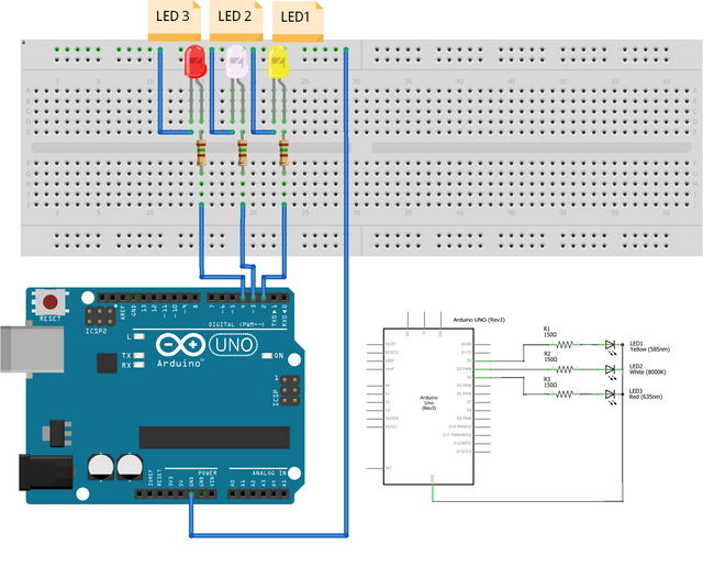
The Wiring Diagram
Below wiring diagram show how wiring should be done based on the code selected output pins (in this case the output pins chosen are PIN 2 for led1 that will be triggered on new upvotes, PIN 3 for led2 that will be triggered on new followers and PIN 4 for led3 that will be triggered on new posts).
int LED_ONE= 2; //pin for led 1 (UPVOTE)
int LED_TWO= 3; //pin for led 2 (FOLLOWER)
int LED_THREE= 4; //pin for led 3 (POST)

                [some other variables are in the code]

void setup()
{
Serial.begin(9600);
Serial.flush();
                                //set the selected led pins as output
    pinMode(LED_ONE, OUTPUT);
    pinMode(LED_TWO, OUTPUT);
    pinMode(LED_THREE, OUTPUT);
}
Materials needed:
- 3x Single Colour LED (Any colour)
- 3x Resistor 150 Ohm
- Jumper wires
The Interface: collaborative testing and implementing
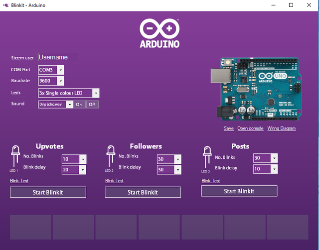
Below is the interface that will be comunicating with Arduino. This interface came out after a series of testing and implementing codes in Blinkit (in coordination with @techtek) in order to match the required setups of Arduino and keep code clean/smooth but very effective.
With the Arduino board connected to the pc with its data/power cable, once the Arduino form is launched in Blinkit, user must enter his username, chose the COM port on which the Arduino is connected and chose the baudrate.
Then the user must chose the led-mode on which to operate (for now only Single Colour Led is available but more modes will be supported soon), chose if to turn on or off sound notification and assign to each led the parameters needed (No. Blinks and Blinkdelay).
Once all done, hit SAVE Button located under Arduino board image so that the settings gets sent to Arduino and saved for later triggers.
Once settings are sent to Arduino, chose which notification to look for and start it by clicking the respective "Start Blinkit" button. At this point the interaction between Blinkit and Arduino is fully setup and once a notification is received Arduino will blink the respective led based on the settings chosen through the interface.
For full details about how the interface works on the code side and how it has been implemented, please get back to @techtek post.
The following files are added to the Blinkit repository
Many updates have been planned concerning Arduino integration. In fact our aim is to let Arduino reach a point where it can become fully automated and do not require to be directly attached to a pc running Blinkit software but will run itself the same tasks as Blinkit software by its own thus becoming a portable stand alone device for Steem related notifications.
Next update we are working on and hopefully will be released soon is the new led mode using RGB led.
Technical Support
Technical support is available, if you may encounter a problem, or if you want to know if your device is supported or will be supported in the near future.
How to contribute?
Do you have a question, or suggestion about the integration of Arduino in Blinkit ? Feel free to contact me on Discord (eliaraysalem#0829) or leave a comment below.
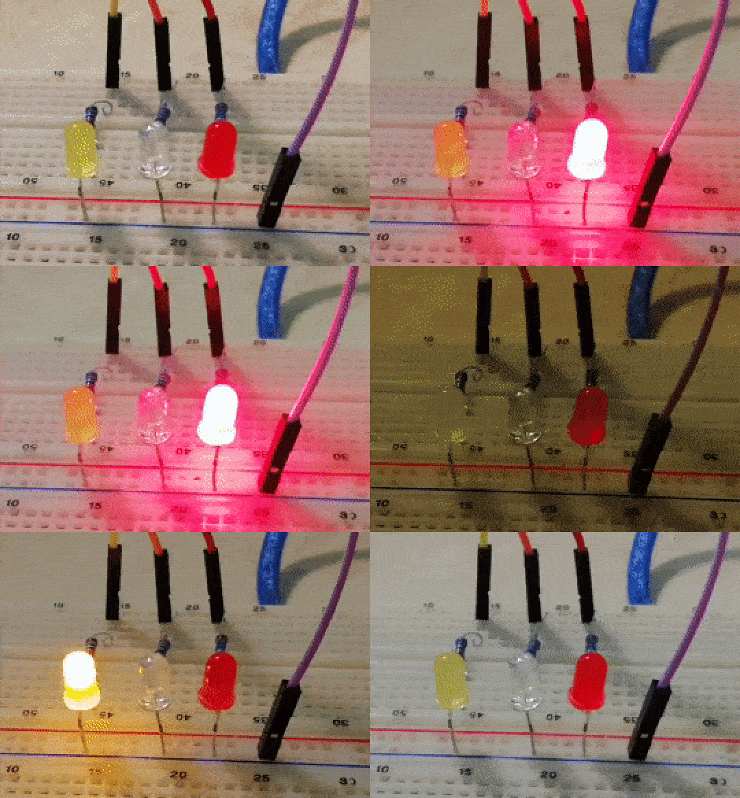
Below my led Blinking with Blinkit !!


Thanks for the contribution!
For future contributions please use your own GitHub account instead of giving it to someone else so they can commit it.
Need help? Write a ticket on https://support.utopian.io/.
Chat with us on Discord.
[utopian-moderator]
Thank you for your review !! will do it for sure !! thanks for pointing out this aspect !!
Thanks for working together, it was a lot of fun and we killed a lot of bugs !
Let's bring even more cool things !
Indeed we had lots of fun !! Owl mode and killing bugs is my new motto !! :D
We will indeed bring lots of new features together and make the worls blink with Blinkit !!
The kit looks highly fancy! I like it!!!
Thanks!!!
Hey @electronicsworld
Thanks for contributing on Utopian.
We're already looking forward to your next contribution!
Contributing on Utopian
Learn how to contribute on our website or by watching this tutorial on Youtube.
Want to chat? Join us on Discord https://discord.gg/h52nFrV.
Vote for Utopian Witness!
Thank you @utopian-io !!
This is a interesting project to follow
Thank you for your comment!! We hope that you will have a try to Blinkit features and to give us some direct feedback by testing it!!