My DIY Passive Mini Radio/Microwave Detector
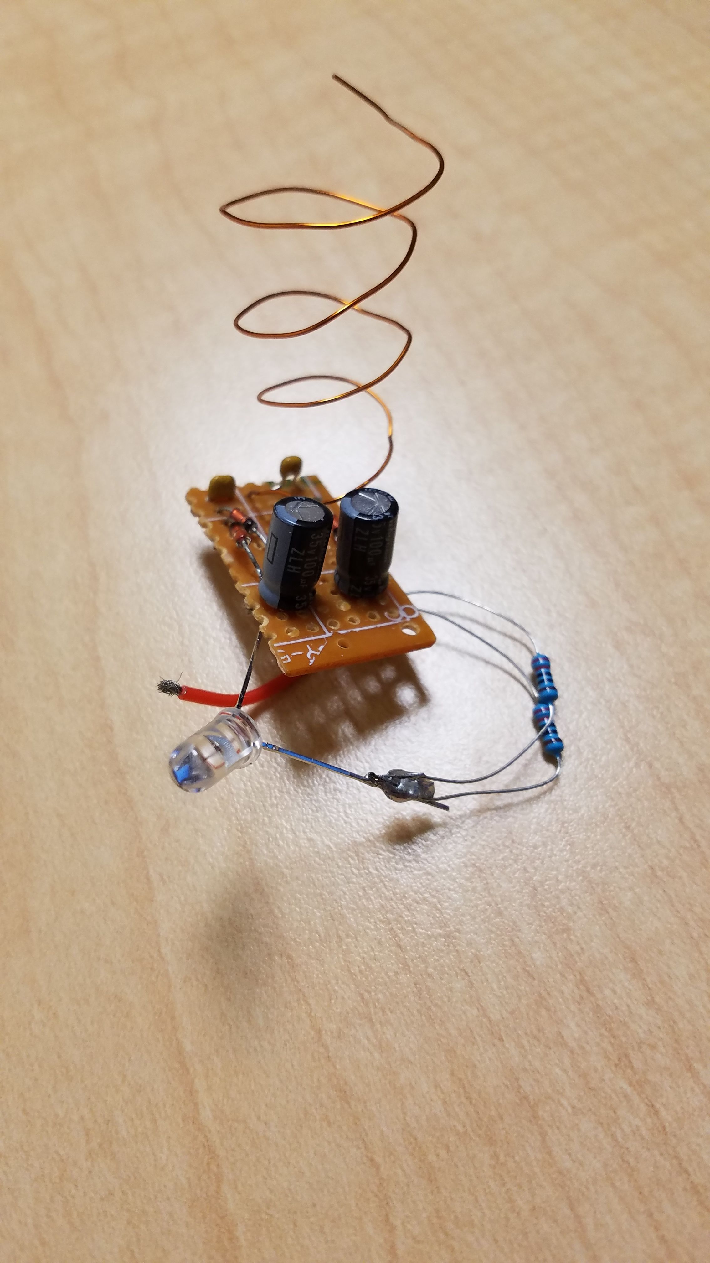
Recently I modified my small radio wave energy harvester circuit (see here for that) into a miniature microwave detector using a super simple modification and a couple extra components. It's a relatively minor modification, but it lets you visibly see when you are near a powerful transmitter: When relatively large amounts of microwave radiation are incident on the crude antenna, the LED lights up using only energy gained from the electromagnetic waves harvested.
This also happens to be a great example of wireless power transfer. The maximum range using the shown antenna is a couple of feet off of a 4 watt transmitter. This could be improved with a better antenna.
Before getting into the circuit, I want to cover a little bit of background so that you can better understand how the circuit works. To avoid repeating to much from the energy harvester post, I'll be quite brief here, so if you want a little more in-depth background I recommend you check out that post (linked above).
Low Frequency Electromagnetic Waves
Electromagnetic waves make our lives possible. High-frequency EM waves let you see things (visible light), very high-frequency EM waves make medical x-ray images possible, and lower frequency EM waves transport the internet to your laptop and phone. You are likely using a Wi-Fi connection to read this post right now, which relies on the use of 2.4 GHz and 5 GHz electromagnetic radiation to transport signals between devices.
Electromagnetic fields, being a combination of oscillating electric/magnetic fields, carry energy - and if we build the proper circuit we can use this energy for whatever we want.

An electromagnetic wave. Changing electric fields produce magnetic fields and vice versa.
Credit
To grossly simplify, when an electromagnetic wave "impacts" a wire, it can induce an alternating current in the wire at the same frequency as the electromagnetic wave. These frequencies vary wildly: AM radio, for example, operates using EM waves with frequencies around 1 MHz while many RC drone remote controllers use waves with frequencies around 400 MHz. Both use antennas to extract a signal out of the inbound wave, but they do not directly use this energy - rather, they use the signal and amplify it using an external power source, usually a battery.
Detecting Microwaves Passively - Making Electromagnetic Radiation do work for you
But there's no reason you can't use the energy in an EM wave to power something else - there just usually isn't much energy in the wave to use. This is the basis for the original harvester circuit, which extracts energy from the air by absorbing microwaves (either ambient or from one of my ham radio transmitters). The circuit (again, [click here] for the full post on this) pulls in an induced alternating current using a crude wire antenna and rectifies it using four germanium diodes. Once the signal has been converted to direct-current (DC) by passing through the diodes, it is deposited into two moderately large electrolytic capacitors, where the captured energy is stored.

Waves approaching a dipole antenna. This project used a monopole antenna instead.
Credit
The newly modified circuit has a small change: I added an LED and current-limiting resistors to the storage capacitors. The result is that the circuit no longer stores significant amounts of energy - rather, captured energy is dumping into the LED to visibly show the user that they are detecting a lot of RF radiation. It literally lets you see where microwave radiation is.
Schematic for re-creating this circuit. Note that this is based on the original energy harvester circuit which I did not design. It is necessary to use 1N34A's or similarly high frequency/low voltage diodes or the circuit won't work - normal power rectifiers will leave you disappointed.
Under ordinary conditions, this circuit does ... absolutely nothing. It takes a reasonable amount of energy to light an LED, and the capacitors have to charge up to the red LED's threshold voltage (something around 1.5 Volts) before current is able to pass through the LED itself, so in most cases the ambient RF radiation around you won't turn on the LED.
But bring the circuit near a strong-ish microwave/radio transmitter and things change. As with the stand-alone energy harvester, waves deposit alternating current on the antenna (a piece of wire) which is deposited in the storage capacitors. Once the storage capacitors reach 1.5 Volts, any additional current can start flowing through the LED, and it glows brightly for you to see. It's a visual indicator that the circuit is in an area with a lot of otherwise invisible microwaves.
Strictly speaking, the storage capacitors aren't actually necessary. I left them in for a few reasons. First of all, they provide a nice buffer between the energy-generating part of the circuit and the LED itself, so the LED stays lit a little longer after you remove the RF source. Second, I didn't want to remove them because I still might convert this back into an energy harvester circuit again if I can't find the rest of my 1N34A diodes (long story). That being said, they don't harm the usefulness of the circuit, and the only downside I can see is not being able to pick up extremely short-lived signals with enough energy to light the LED.

I used capacitors like the one shown but with slightly higher voltage ratings as the storage capacitors. These are very easy to find in old electronics. You won't run into any over voltage issues with this circuit because the LED will dump excess charge unless the inbound RF power is enormous.
Credit
By the way: It is actually important that the LED is red. Red LEDs have the lowest voltage drop across them of visible light LEDs (infrared LEDs or IREDs have lower voltage drops), which means that red colored LEDs will be able to pick up weaker signals than say blue LEDs.
If you can't tell yet, this circuit was thrown together in a hurry. Note the two 220 ohm resistors: This was done because I added one, didn't think it worked well enough, then added a second one to drop the overall resistance and increase the brightness. It worked, so I never bothered to remove them and just go add a single 110 ohm resistor in their place (two 220 ohm resistors in parallel are equivalent to one 110 ohm resistor).
Trying out the detector
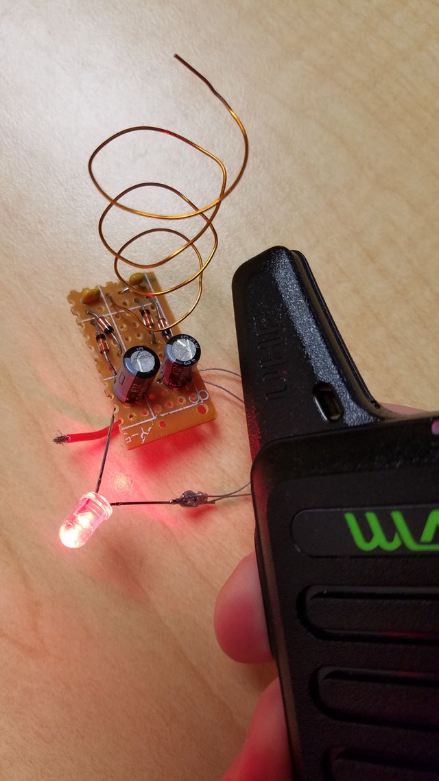
Here's the circuit in use, detecting microwaves around 430 MHz:

The microwaves are coming from that handheld radio transmitter, transmitting around 430 MHz with a power of somewhere between 1 and 2 Watts. The transmitting antenna is very close to to the detector, so the LED glows brightly.
Remember that there is no power source onboard the detector! The light you see is generated using energy that was extracted directly from the microwaves. In essence, the LED is being powered off of the black radio transmitter's internal battery even though there are no wires joining the two devices. Pretty cool!
You may ask, why the curled up antenna? The answer is, I don't know. I was originally using a straight wire folded over itself once, but the people I showed this to curled up the antenna and it seemed to work a little better for ~400 MHz signals so I went with it. Plus, it's more portable this way!
I had the best results detecting radiation around the 400 MHz part of the spectrum. The circuit is able to detect lower-frequency ~140 MHz radiation but at a lower efficiency (I suspect this is due to the short antenna). Unfortunately I don't think it will be able to pick up Wi-Fi frequency microwaves, both because the 1N34A diodes probably can't handle 2.4 GHz and because it's difficult to obtain a relatively strong source of this radiation without microwaving the circuit. By using higher frequency diodes and a proper antenna, though, there is no reason this wouldn't work. I've seen circuits like this online used to check for microwave oven leaks.
By moving the microwave source towards and away from the circuit, you can fade and brighten the LED, showing how strong the RF source is. This circuit could be used, for example, to find hidden FM transmitter microphones if you are the paranoid type. Really it can be used anytime you want to quickly figure out if there is a lot of RF radiation in your vicinity (But remember, RF isn't dangerous, so please don't go using this for health reasons...).
Bonus: Even smaller mini microwave detector
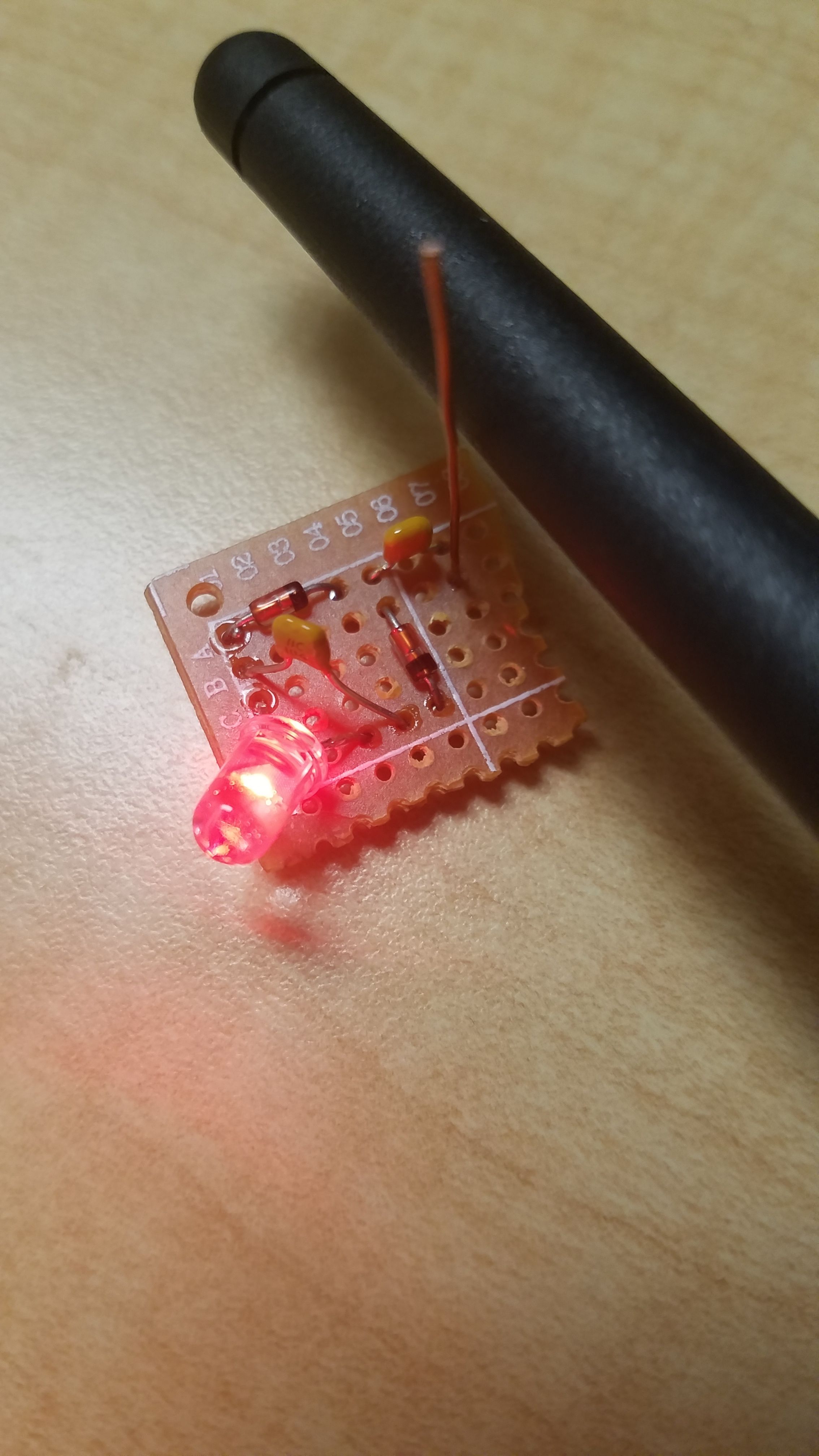
While writing this I decided to search my parts box and sure enough found a smaller version of this circuit (with just 2 1N34A diodes and 2 capacitors) that I built this past summer. I had planned to use it to try and pick up cell phone signals but it didn't work. Turns out that I just needed a bit more RF power - it works somewhat well of my transmitters. It doesn't work quite as well as the 4-diode detector covered in this post, but it's still an interesting little gadget. This one uses a 100 nanofarad capacitor in place of the big storage capacitors used in the previous detector, and as such requires much less energy to initially turn on the LED.

This is my original detector from months ago that apparently actually did work. Here you can see the circuit producing light from ~400 MHz RF radiation produced by the visible black antenna (4 Watts). The antenna is stupidly short, and it works better when you attach an alligator clip wire as an antenna.
Unlike some of my other projects, I highly recommend that you go out and build this yourself! It's pretty easy to do and I think the circuit is a really cool way to visualize wireless energy transfer and radio-frequency waves for yourself. No safety issues this time, this thing is totally safe to use.
If you have any questions, comments, or corrections, do not hesitate to let me know. I hope to do more work on these kinds of harvester/detector circuits. In particular, I'd like to get one working with 2.4 GHz radiation so it can pick up WiFi (this will require new diodes and a new design) and perhaps a flashlight that can trickle charge in your pocket from ambient RF (this is a bit more of a long shot).
Thanks for reading!

This Baofeng walkie talkie is a good example of something that will set off this detector and make the light glow.
Credit
Additional reading on antennas and RF:
Radio Antenna Wikipedia Entry
RF/Radio-Frequency Wikipedia Entry
ExplainThatStuff: How Antennas Work
RFID Wikipedia Entry - Passive RFID tags work similarly to this detector.
NOTE: Do not use ham radio transmitters without a license and ensure that the channel you are using isn't in use before transmitting to test circuits like this. I kept all of my transmissions extremely brief to avoid unwanted interference. If you want an easier way to test this circuit, low-power walkie-talkies are available online for cheap.
Images not credited are my own. You are welcome to use them with credit.


Good innovation, you made me remember to Tesla and his project, this allowed through electromagnetic waves to obtain energy. "You may ask, why is the antenna rolled up? The answer is, I do not know." I think, it may be because of the wave intensity that the antenna catches thanks to its spiral shape. With an electromagnetic viewer you can visualize how the radiation is concentrated in the middle of the spiral.
Thank you for sharing this simple piece of engineering. It is the useful little gadget for people concerning about EMF.
Closely related to this post about dangers of 5G.
Keep in mind that it will only currently respond to pretty strong signals (ie within a few feet of multi-watt transmitters). I hope to improve that in the future, however conservation of energy places some limits. But this circuit with a better antenna should work well!
Yep, I know it... Saw an examples what levels of power needed to light up similar things.
One example below (guys from Lugansk, lang: russian)
In this video guys made a plate with lights to check if MW radiation is properly directed.
The power of MW oven is 750W or similar, I believe.
I love those Luhansk guys! In this case the magnetron is so high powered that you don't even need to build a circuit to light up stuff like gas tubes, everything is excited by the sheer number of microwaves. Those guys produce a lot of good videos, which is even more amazing considering that they effectively live in a warzone (you can here a bomb fall in the distance in one of the videos).
I would say CRrAzY$&^%^*&^ but I also love what they do...
I remember the video when they was attracting a lightning w/ MW magnetron...
KREOSAN
Wow! Well written. I wish I could have that much knowledge.
Wow. Great execution and attention to details. Thanks for sharing PCB Technology : Flexible PCB