How stuff works - Gear systems PLUS an activity
As a continuation of my previous post about Pneumatic and hydraulic systems, and because boys love love love learning all kinds of new stuff about technology, I decided to add "how gears work" as a sequel.
I remember how fascinated I was with gears as a young boy. The way they operate brought me hours and hours of entertainment. It's very stimulating just to watch gears do what they are supposed to be doing, but even more so when you get the opportunity to piece them together like a puzzle:

What is a gear?
A gear is a wheel with evenly spaced teeth on the surface. The shape of the teeth on a gear varies depending on the job the gear has to do.
There are different kinds of gears
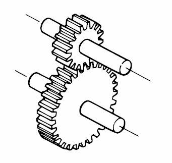
- Spur gears

Spur gear
A salad spinner is used for drying washed lettuce: the gear wheels turn the spinner at a high speed, even though the spinner’s handle turns slowly. Centrifugal force makes the water move outwards through the holes in the spinner.
At the end of this post, I will give more detail about Spur gears.

- Rack and pinion

Image source
Car steering wheels use gears, levers and reds to turn the wheels. The steering wheel is connected to the rod called the steering column, and together they work as a wheel and axle. A rack and pinion moves the rack, which is linked by rods and levers to the wheels.
- Bevel gears

Bevel gears are used to change the direction of the drive in a gear system by 90®. They are used in the main mechanism of a hand drill. As the handle of the drill turns in a vertical direction, the bevel gear changes the rotation of the chuck to a horizontal direction
- Worm gears

Worm gears look unusual: a rod with a screw thread around it is connected to a gear wheel. The gear wheel turns in a different direction. The gear wheel can also turn the rod
How do they work?
- When two gears are put together, it is called a gear train.
- The teeth of the gears fit into each other; this is called meshing.
- It is very time-consuming to draw all the teeth of all the gears every time you draw a gear system. That is why we can use plain circles to represent gears in drawings.

- The picture above shows a system diagram of a gear system.*
- Gears can transfer movement between shafts in a mechanical system.
In a simple gear system there are two gears:
- The drive gear is powered by a motor
- The driven gear turns as a result of the force of the driver gear.
- The driver gear providers the input (force and speed) and the driven gear provides the output.

Gears can change the direction in which the shaft rotates.
When one gear is meshed into another gear, the gears will turn in opposite direction.
When an idler gear is used between the driver gear and the driven gear, the direction of the driver and driven gear will be the same.
The idler gear will not change the speed of the gear.
When calculating the speed ratio in a gear system, we do not look at the diameter of the gear as we do when working with pulleys, but we look at the number of teeth on the gear.
The ratio between the speed of the driver gear and the speed of the driven gear is known as the speed ratio.
Speed ratio is also called velocity ratio.
Speed ratio is calculated by dividing the number of teeth of the driven gear by the number of teeth of the driver gear.
When the gears have the same number of teeth, the driven gear will rotate at the same speed as the driver gear.
When there are more teeth on the driver gear than on the driven gear, the driven gear will rotate at a faster speed.
When there are fewer teeth on the driver gear than on the driven gear, the driven gear will rotate at a slower speed.
To calculate the speed ratio of gear system you can use this formula:

Example
The number of teeth of the driven is 120 and the number of teeth on the driver gear is 30:
This means that with one rotation of the driver gear, the driven gear will rotate four times.
Spur gears
- Spur gears are the most common type of gears.
- They look like the spurs worn on riding boots to make a horse move faster.
- Spur gears have straight teeth.


- The shaft that they are attached to are parallel to each other.
Activity:
Calculate the speed ratio of the following gear system:
The number of teeth of the driven gear is 260 and the number of teeth on the driver gear is 180
Bibliography & Extra reading:
- Elements of metric gear technology PDF
- Bevel gears
- Rack and pinion
- Worm gears
- Levers, linkages and gears
- Gears and gear ratios
- Gear speed
- How Spur gears work
Watch out for my next post about Machines & Energy

Keep up the good work
Good Job
Gear systems are fascinating, and the 'How Stuff Works - Gear Systems PLUS an Activity' article does a great job explaining their mechanics. It's impressive how the activity helps to visualize the concepts in action. For anyone exploring this, even setting up a simple system on a virtual server, like using a vps indonesia service, can add an extra layer of engagement and learning.