Telecommunication Principles #1: Microwave Transmission
Greetings to every wonderful steemian out there, I'm excited to bring to us a telecommunication series which is aimed at creating awareness to the fastest growing technology. At the heart of information and communication technology is telecommunication, the enabling infrastructure is all around us but most of us have no clue about the technology. I'm starting this series with microwave transmission and at the end of this post, most of us will look up at that tall telecommunication mast and say a long "Okay".
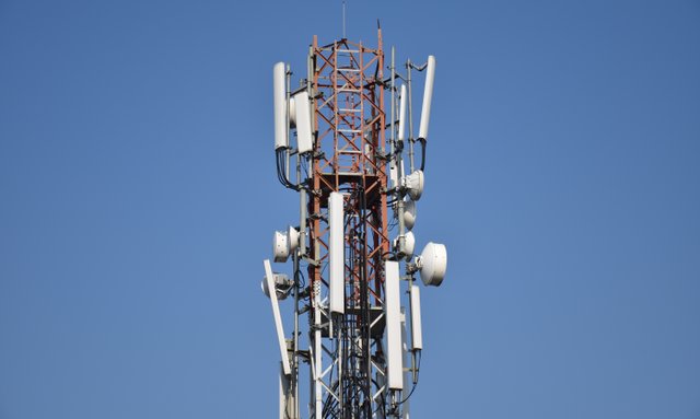
A telecom mast showing various sectorial and microwave antennas. Image source Pxhere. CC0 creative commons license
I looked for a subtle way to start this post and it seemed to be the most difficult part of putting up this post from my end. I'll will start by first answering this question, how did we get here? We have about four broad medium of digital transmission and they include optical transmission (fiber optics technology), Cable transmission (coaxial, twisted pair, straight pair, etc.), Satellite transmission (VSAT, etc.) and Microwave transmission. Due to speed and weather dependency of VSAT technology, it is rarely used by modern service providers though the field of satellite internet has undergone serious reform and could transmit at a staggering rate of 1000Gb/s and are not common.
Cable transmissions (copper connects) are no longer used for connecting high speed devices that span a long distance. Most copper cables can only carry signals for a maximum distance of 100 meters, hence to achieve transmission with copper cables above 100 meters, signal amplification and noise filtering devices called Repeaters are placed in the system before the cable spans up to 100 meters. This is because the resistance of copper cables (which are good conductors) increases with increase in length, consider the equation below:
R=Pl/A
where l = length, A = cross sectional area, R = resistance and p = Resistivity
From the above formula, the only way to reduce the resistance is to use a cable with higher cross sectional area. Now imagine your coaxial cable which you're using to connect your television system is made to have a diameter of say 2 centimeter, apart from failing international standards, it is also no economically feasible. Fiber connectivity is the most widely used medium, you can find my post on fiber optics technology here. Major drawbacks of fiber optics connectivity is that it is very expensive and always requires experienced hands for maintenance and installation.
Microwaves
To put it very short, microwaves are approximately plane and electromagnetic waves occupying frequencies in the range of 300 MHz to 300 GHz. I'll break down the above sentence. I say approximate because in reality, no wave is perfectly plane. For a wave to be perfectly plane, it must posses constant amplitude and constant frequency with infinite points experiencing the same amount vibration (wavefront).
Microwaves are also transverse waves (in contrast to longitudinal waves). They're called transverse waves because they travel at angle 90o to their source. Hence if a signal generator is placed horizontally, the generated waves will travel vertically. They are electromagnetic waves because their production is as a result of interactive vibrations between electric and magnetic field.
In telecommunication, microwave transmissions are done within the frequency range of 3GHz to 30GHz. Frequencies less than 5 GHz are known as unlicensed frequencies, hence, signal generators that operate at frequencies less than 5 GHz are called unlicensed radios and can be used anywhere without the interference of local authorities.
))
Repeater station or relay stations are used to ensure that signals get to their destination, the repeater shown above is a passive repeater because it doesn't offer signal amplification or noise filtering. Image credit Wikimedia. Creative Commons license.
Hence, microwave transmission refers to the processes of conveying digital information using microwaves as carriers. It has quite a number of advantages, little wonder it is everywhere in the city. Unlike any other means of transmission, microwave transmission can span a great distance carrying information at mind blowing speeds, hence eliminating the need for land and is mostly unaffected by land privation acts.
Setting up microwave transmission system also takes the least amount of time and requires relatively little funds when compared to its counterpart, like the fiber connectivity. Its major down side is the limited amount of frequency resources. As stated earlier, only frequencies within the range, 3 GHz to 30 GHz is available for microwave transmission and many of these frequencies are also in use by other technologies. They're also affected by weather and climate but not as much as it's counterpart, the satellite communication.
Baseband Frequencies (BF), Intermediate Frequencies(IF) and Radio Frequencies (RF)
Microwave transmission is all about waves and this include wave properties like frequency, amplitude, phase and speed. Of importance are the frequencies we employ in the course of this transmission and these are baseband frequency, intermediate frequency and radio frequency. Radio frequency or radio wave is a name given generally to high energy waves. It can be seen as a reference point which shows the rate of vibration of electromagnetic waves. The range of radio frequency is not generally accepted but often, it is believed to be in the range of 20KHz to 300GHz, this makes microwave a subset of radio wave. At the receiving point of the antenna, what is received is called radio wave or radio frequency.
A typical digital signal (baseband signal) in a radio frequency format (amplitude modulated double sideband form) showing increased bandwidth. Image source Wikimedia. Creative Commons Attribution-Share Alike 3.0 Unported license.

I'm certain most of us have heard about baseband signal or baseband frequency, but what really are they. Talk about technology that employs signal modulation and demodulation, and I'll tell you it's telecommunication. In simple terms, modulation is the act of wrapping weak signals inside stronger signals to aid the transmission of the weaker signal. At signal reception point, the weak signal is removed from the stronger signal and this is known as demodulation. A device whose main function is is to constantly carryout the above activities is called a modem. Modems are found in many points in telecommunication.
Baseband or (BB as it is mostly called) are the base signal, or the signal of interest. This is the form our signal takes before it is modulated. On the reason why modulation and demodulation is important, someone might ask, why can't our voices travel very far, like miles? The answer to this question lies on the type of wave, the frequency and this ultimately determines the speed. Sound is a longitudinal wave and hence, suffers compression and rarefaction. No matter how we increase our pitch, the difference it makes is not much. Same with baseband signals transmitted through the air without encapsulating it in a higher frequency electromagnetic and transverse wave.
A technology that can transmit baseband signal without the need to change its form, i.e, modulation and demodulation is the twisted pair cable transmission also known as Ethernet. Some of the IEEE ethernet specification clearly indicates this and we have specifications like the IEEE 802.3 10 Base T, the "base" in the name means baseband signal or in this case, ethernet signal.
The word intermediate means in-between. The intermediate frequeny is a product of radio frequency and the signal of interest (baseband signal). To obtain the intermediate frequency, we perform a trigonometric identiy of RF and baseband signal, this is known as superimposition. Consider the relationship below.
where fa and fb are the radio frequency and baseband signal respectively
The above formula splits the wave into two components, the sum and the difference components of the two frequencies. The intermediate frequency is the difference component of the above superimposition, i.e
the resultant difference component is made an absolute value to eliminate negative values.
Intermediate frequency sits in between the base signal and radio signal (carrier). Modern microwave systems include intermediate frequency processors in their designs and are hot swappable in a form normaly called an "IF card".
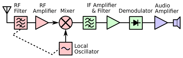
A block diagram of a superheterodyne receiver showing the radio frequency (RF), baseband signal generator (local oscillator) and the intermediate frequency IF, this is for audio system, it is a general form for microwave systems. Image source Wikimedia. Creative Commons CC0 1.0 Universal Public Domain Dedication.
But is conversion to intermediate frequency really neccessary, why not convert an incoming signal straight to baseband signal? A system that converts radio signal straight to baseband signal is called homodyne receiver while a system that converts RF to IF before finally extracting baseband signal is known as heterodyne receiver.
On the reason why modern microwave receivers are heterodyne system is a bit beyond the scope of this write up but I will clear up the air a bit. We use different microwave frequencies for different purposes but irrespective of the microwave frequency in use, a receiver system should be able to automatically process the incoming signal. Signals used for microwave propagation are lower 6 GHz, 7 GHz, 8 GHz, 11 GHz, 13GHz and so on (I'll discuss this shortly), a homodyne receiver is incapable of processing widebands such as the frequency series above. A grasp of these three frequencies is a key to understanding microwave transmission.
Radio Access Network (RAN)
RAN and LAN, seems like they sound alike right? LAN has been discussed extensively by me and many prolific writers in the stem community, hence, I'll assume we all know what LAN is, for reference sake, checkout my post about LAN here. Just like local area networks (LAN), RAN also have topologies and designs, lets discus the former.
RAN designs
Every RAN is hierarchically designed and segmented into three major parts. This design might not be obvious from physical observation but conceptually, it always follow a hierarchical pattern. Here, the network is divided into three parts and these are:
- Core Network
- Convergence Network
- Access Network
The main aim of every telecom network is to connect all users to the core network, but it is simply impossible to connect all users directly to the core, hence the need for the access and the convergence networks. In a telecommunication system, the only intelligent part of the network is the core. This is where the mobile switching center, billing system, customer management servers and interfaces for connection to other service providers are all situated. For someone in Enugu state making a call (for example using GLOBALCOM network) to someone in the same state, the call is routed through various RAN to Osun state where all the billing and major switching is carried out, and the call is routed back to Enugu where the call destined. Though there may be more than one core network, this type of design is called a distributed core network.
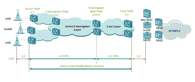
The necessary servers and switching elements are found at the core network, unlike the core layer for LAN networks where intelligence is added in all layers of the network. Original image available at ZTE. Creative commons license.
The network link between the access network and convergence network is known as the backhaul, also the link between the convergence network and the core network is known as the backbone. The convergence network is serves as an aggregation point of the network where all the access links are connected to. Modern telecom network design employs less microwave transmission for the backbone, nowadays, fiber optics cable are used to pickup traffic from the convergence network to the core network though microwave radios are still seen in many backbone links.
Access networks interfaces directly with the users, hence they're usually called terminal sites. Most terminal sites have only a single Microwave radio hoisted on the mast.
RAN network designs are majorly of four different types and depending on the network segment, location and the amount of traffic estimated to pass through the link. These network topology are Ring, Chain, Add/Drop and Hub network topology.
In the ring topology (similar to the token ring in LAN topology), the microwave antennas are arranged in form of a circle, spanning over large land areas. Each station in such a cell acts both as a repeater and a transceiver and should one link on circle fail, the network will continue to operate but this time as a chain network topology. The chain network (similar to the bus topology in LAN) is the arrangement of microwave systems in such a way that one station links to another station in a back-back manner. The chain topology can still be seen in modern network but not in a high availability designs.
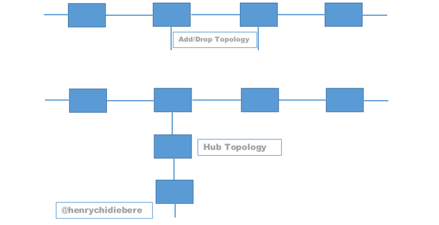
the two unpopular microwave network topology. Image designed using MS Word
The add/drop network as the name implies are chain topology with provision for connection to other networks (network of higher or lower hierarchy). The add/drop network adds more redundancy to the network than the traditional chain topology. The hub topology is also similar to the add/drop network but in a branching fashion. In reality, the hub connection points are characterized by the heavy microwave antenna presence. This topology is widely employed in the microwave transmission system.
Microwave antenna and principles
In mobile telecommunication, we use majorly two types of antenna, the microwave antenna and the sectorial antenna. Physically, the microwave antenna looks like a drum (see the image below), this type of antenna is known as horn antenna. The microwave antenna is used majorly for point to point connection, radiating signals in a concentrated manner with the ability to transmit these signals for a longer distance than the sectorial antenna.
))
Microwave antennas of different diameters. The diameter ranges between 0.6 meters to 3.2 meters. Stations at the backbone uses large diameter and small transmission frequency, usually between 6GHz to 8GHz. Last mile or backhaul links uses antennas with little diameter (from 0.6 meters to 1.2 Meters) and high frequency (from 13GHz to 30GHz), these are licensed frequencies. Image credit Wikimedia. Creative Commons Attribution 3.0 Unported license.
The sectorial antenna (the white colored antenna that looks like a classic fluorescence lighting unit in the home) radiates at a specified angle, say 120o, 90o and so on. It is used for signal broadcasting rather than signal transmission, hence, in sites which requires 360o coverage, three sectorial antenna that have radiating angle of 120o, or four sectorial antenna that have radiating angle of 90o is required. Not every site is intended to broadcast signals, areas where there are little or no population like the desert or forest have no sectorial antennas installed.
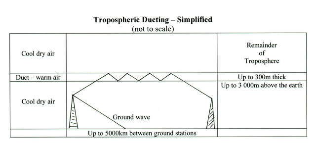
The microwave antenna communicates only when there's enough line of sight (LOS) between two terminals. This is not the same with the sectorial antennas. Hence, if the antennas are not seeing each other, there won't be any communication, unless in rare conditions where hot air affect the normal refractive index of a particular atmospheric region between two antennas causing signal redirection to unintended destination, this condition is known as ducting.
How atmospheric ducting could be used in communication, but they could form in between radios and disrupt signal transmission totally or for a specific period of time. Image source Amateur radio wiki. Creative commons license
,_satelity_s_v%C3%BDhledem_do_krajiny.JPG)
When signals leave a microwave antenna, they spread out and form what is known as Fresnel zone. They recollect at the receiving end and amounts to the total signal received by an antenna. Without two antennas seeing each other, there won't be optimal communication or any communication at all.
))
Signals arriving at station B do so with some delay but this is corrected by the receiving antenna. Blockage of more than 30% this zone (Fresnel) will greatly hinder signal transmission. Image credit Wikimedia. Creative Commons license.
In fact, for maximum reception of signal, the barrier between the line of sight must not be more than 30% of the Fresnel zone, at the 40% mark, no signal reception will occur ( see the image above).
I hope that this has been informative for you and I'd like to thank you for your time
REFERENCES
- Microwave transmission ~Wikipedia
- Microwaves ~Livescience
- The benefits of an intermediate frequency (IF) in RF systems
- Radio access network (RAN) ~Wikipedia
- Baseband signal ~techterms
- Fresnel zone ~wikipedia
If you write STEM (Science, Technology, Engineering, and Mathematics) related posts, consider joining #steemSTEM on steemit chat or discord here. If you are from Nigeria, you may want to include the #stemng tag in your post. You can visit this blog by @stemng for more details. You can also check this blog post by @steemstem here and this guidelines here for help on how to be a member of @steemstem. Please also check this blog post from @steemstem on proper use of images devoid of copyright issues here.

An upvote for a few cents from the German-speaking community of the German-Steem-Bootcamp
Wow , great post even for a rookie like me!
In fact, to find a telecommunications company is not easy, and here it is better not even to think, and immediately contact the professionals. That's what I did, and I recommend others do, for example. You can look here roku phone number and contact them. I already know that I managed to find just the right people here who were able to configure everything for me and now there are no problems with the Internet and television. Good luck, I hope I was able to help someone!