Everyday Electronics part #1: Resistors
Welcome to this fun series of everyday electronics where I get you very close to electronic components and their basic usage, internal workings and how to recognize them.
Resistors, yes resistors. Resistors are one of the very basic electronic and electrical component in the sense that they can handle both high current and voltage (just like every other electrical components) as well as very little current and voltage (just like every other electronic components). Resistors are components that oppose the flow of electrons in a circuit. One would ask, why oppose the flow of current when the generation of current was a very costly process and hence should be allowed to flow freely?

credit: wikimedia
Well, we should think again because the torque generated by our car engines also underwent a costly process, yet brakes were added to vehicles. When the flow of current is controlled, it can be maximally utilized and this is where resistors comes in.
Resistors in it most basic form is a two terminal passive component capable (for through-hole coupling) of implementing resistance to a circuit. It is a passive component because it only consumes the power in a circuit without the capability of generation. Depending on the target component, resistors can be composed of film of metal-oxide, carbon or even metal.
Metal film resistors
In metal film resistors which is one of the most common type of resistors, sputtering (also known as vacuum deposition) technique is used to coat the ceramic rod with nickel chromium (NiCr) and the resistance value determined usually by making a helical cut on the coating using lasers The NiCr is the actual resistive material but for specialized application, some metal alloys can be used. These alloys include the alloy of tin and antimony, alloy of gold with platinum and many more.
The resistance of the resulting resistor mainly depends the thickness of the deposition usually between 50nm to 250nm. There is usually a trade-off between the stability of the resistor and the resistance value, therefore higher thickness of the deposition means more stability for the resistor but less resistance and vice versa. Metal film resistors are very popular because of their high tolerance (sometimes up to 2% tolerance value), good temperature coefficient of resistance (TCR) and great stability.
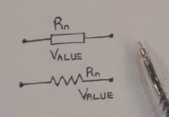
Symbol
))
credit: @henrychidiebere
Resistor color codes
The bright colors spotted on metal film resistors are not for graphic design purposes. Due to the size and shape of these types of resistors, their values are coded on their body using colors and I am going to point out here how to read the resistance value of these resistors by mere looking at them.
The first step in reading the color codes on resistors and determining their resistance value is to identify either of these colors; silver and gold. The silver or gold color indicates the tolerance value of the resistor. The tolerance value indicates the amount of deviation of the resistor from the ideal resistor, hence a 100 ohm resistor with a tolerance value of 5% will provide resistance of about 100ohm plus or minus 5ohms. Most metal film resistors have four color bands.
Once you establish the gold or silver band on the resistor (which is always a bit away from other three bands), the first color band is the band farthest from this tolerance band. This first two color band is the resistor's most significant digit while the third band denotes the weight value and this means value of the power of ten which will be used to multiply the two most significant digits. The values of the resistor color bands are shown in the table below.
| color | digital value | multiplier | value of multiplier |
|---|---|---|---|
| Black | 0 | 10^0 | 1 |
| Brown | 1 | 10^1 | 10 |
| Red | 2 | 10^2 | 100 |
| Orange | 3 | 10^3 | 1000 |
| Yellow | 4 | 10^4 | 10000 |
| Green | 5 | 10^5 | 100000 |
| Blue | 6 | 10^6 | 1000000 |
| Violet | 7 | 10^7 | 10000000 |
| Gray | 8 | 10^8 | 100000000 |
| White | 9 | 10^9 | 1000000000 |
The gold color band has tolerance value of 5% while the silver color band has tolerance value of 10%.
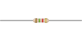
For example, we will determine the resistor value of the resistor image shown on the left.
Its very obvious the resistor tolerance band is gold in color hence the tolerance value is 5%. Also the first two colors are brown=1 followed by green =5, hence concatenating them both gives 15. The third color band which is the multiplier is red which from the table above is 10^2=100. Hence the resistor value is 15*100=1500ohms. This makes the resistor to be equal to 1505ohm or 1495ohm as indicated by the tolerance value. If this method is difficult to follow (which i think it is not) you can checkout an easy tool for the color calculation here on Sparkfun.
The variable resistor
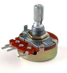
Just like the name implies, variable resistors can provide varying amount of resistance in a circuit. This is done by providing as many point as possible on the resistor which can be tapped. This tapping is possible because variable resistor unlike other resistors have three terminals with the third terminal being the movable tapping terminal.
The potentiometer is a very good example of the variable resistor as its application is very close to the average user level in circuits. This is found in the volume adjuster of our FM radios. The resistance offered by this type of resistor can be varied by rotating the knob for the volume adjuster type, or by using a flat screw driver to select the desired resistance for the breadboard type, or by sliding to the required resistance for the slide pot type, which ever variable resistor type, the adjustment method can easily be figured out.
Variable resistors are usually constructed using flat resistance material usually composed of carbon, metal film coating, or a plastic capable of electrical conduction as the base material. The tapping contact is usually made with a spring-like bronze in the form of a wiper and can move along the surface of the base material. Variable resistor can also be made using a resistance wire which is wound on a base (metal, or carbon) with the slider moving along this coil.
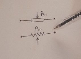
Symbol
))
credit: @henrychidiebere
The position of the arrow can be either at the top or under the symbol. The resistor label is also crucial for reason already stated above. Since the value of the resistor is variable, the highest resistance obtainable with the resistor can be appended as the value or the actual resistance required at that resistance point can be appended as the value of the resistor.
Resistor Arrangement
By default, it is always very difficult to get the exact resistor value required by a circuit from a single resistor. It either the available resistor is greater than the required resistance value or it is less than the required resistance value. Basically, resistors are arranged either in parallel or in series. Knowing the arrangement of resistors is a crucial knowledge in building not just safe circuits but a functional one.
Example, if I have 200ohm, 100ohm, 2kohm and 50ohm resistors connected in series, their total resistance is given as 200+100+2000+50 = 2350ohm. Hence if I need 2350ohm resistor in my circuit and I have the above four resistors, I can connect them in series and get the needed resistance.
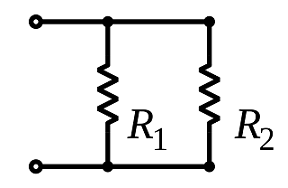
When resistors are connected in parallel, their total resistance is not as straight forward as the arrangement in series. For the parallel arrangement, the inverse of the total resistance is given as the summation of the inverse of the individual resistor values in the parallel connection. Mathematically; >1/Rtotal = 1/R1 + 1/R2 +..... + 1/R(N-1) + 1/RNParallel connection is shown in the image to the right. For example if i have the same amount of resistors values as stated above, the total resistance in parallel is given as
1/Rtotal = 1/200 + 1/100 + 1/2000 + 1/50 = 0.0355, hence Rtotal is given as the inverse of 0.0355 which is approximately 28ohms. Hence the resultant resistance is far less than the smallest resistance in the circuit.
Power of a resistor
The power rating of a resistor can be linked to its sized for a metal film resistor and for many other resistor types or it can be written explicitly on the body. For this post, we will determine the power rating of metal film resistor experimentally using a multimeter and a voltage source. To experimentally determine this, the Ohms low is used and it states that the measure of current between two point of an electrical conductor is directly proportional to the voltage across that same point. Mathematically;
I = V/R
To experimentally determine the power through a resistor, connect the resistor in series to the voltage source and then measure the current between the terminals of the resistor. with these two values, the power of the resistor is given as;
P = I*V
Applications
Resistors are crucial component in any circuit and is in fact part of almost all electrical and electronic circuits. Resistors are applied as a current limiting component, in voltage dividers, voltage pull-up and pull-down, etc.
Voltage dividers
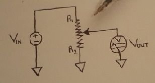
Just as the name suggest, voltage divider circuits are circuits used in providing smaller amount of voltage from a larger voltage value. It is purely a passive circuit consisting of resistors and input voltage. For this purpose, the resistors are arranged in series and desired fraction of voltage is obtained as a function of the input voltage and the resistor value and arrangement. to obtain the desired voltage, this formula is used;
Vout= Vin [R2/(R2+R1)]
))
credit: @henrychidiebere
Current limiting
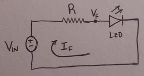
Resistors are used in reducing the amount of current flowing to some delicate device especially led. Light emitting diode in many electronic circuits are very delicate and voltages as high as 5volts is enough to render the component useless. When resistors are arranged in series with the target device, the desired current can be delivered to these components.
When trying to figure out the size of the current limiting resistor for a Light emitting diode, two crucial values are considered, maximum forward current required by the led and the forward voltage of the led.
))
credit: @henrychidiebere
With the two values above, the required resistance can be determined using the formula below;
R = (Vin - Vf)/If
For example, if the voltage input to a led through a battery source is 12v, and the forward voltage of the led is 2volts. If the required current in the circuit is say, 20milliampere, then the required resistance is given as
R = (12-2)/0.012 = 833.33 ohm resistor value.
Reference
- Resistors -Sparkfun
- Resistors -wikipedia
- Voltage divider -solved problems
- Resistor Power rating -electronics tutorial
If you write STEM (Science, Technology, Engineering, and Mathematics) related posts, consider joining #steemSTEM on steemit chat or discord here. If you are from Nigeria, you may want to include the #stemng tag in your post. You can visit this blog by @stemng for more details. You can also check this blog post by @steemstem here and this guidelines here for help on how to be a member of @steemstem.


))
))
))
))
))

This is a test comment, notify @kryzsec on discord if there are any errors please.
Being A SteemStem Member
Hello - Awesome article! One thing I have been trying to figure out is the difference between a Potentiometer and a Rheostat. I found this article which touches on it briefly https://www.derf.com/rheostat-overview-article-and-video-explanation/ but I still don't understand fully. Does anyone know the difference? Because from what I can tell they are very similar .. Thanks!
Hi. You are doing what I want to do. I am an electronic engineering student and I want to contribute this community like you.I am posting abaut my department. I followed you. Keep it up :)
Feel free, let your contribution be known. Thanks
Fantastic
Number 3
Slave Gain = -0.9475