DIY Spark-Gap Radio Transmitter and Explanation
The first radio transmitters of the early 1900s were known as spark-gap transmitters. Spark-gap transmitters rely on a plasma arc from a high voltage supply to rapidly dump energy into a coil/antenna and produce radio-frequency oscillations, resulting in production of electromagnetic radiation. Spark-gap transmitters were used even before the advent of vacuum tube technology, and saw use as the sole radio transmission technology prior to World War I.
Spark-gap transmitters are also really easy to make, if you don't mind the final product being somewhat crude. That's what I've done today, and I'll be sharing how these devices work and how the (temporary) one I built performs.
As always, before getting into the details, here's what the final product looked like:
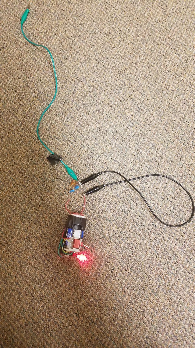
The green alligator wire serves as a crude antenna. Don't worry about the carpet... this HV supply can't even light paper on fire, let alone carpet ...
Spark-Gap Radio Transmitters: Principles of Operation
The core of a spark-gap transmitter is a high voltage supply. Several thousands of volts need to be produced to be able to produce an electric field strong enough to ionize air across a gap and produce the spark-gap itself. Anything over around 5,000 volts should work well. In this case, I'm using my mini stun gun I built a few days ago (writeup on it here) to drive the oscillations that will produce electromagnetic waves.
But why is a spark-gap needed? Before getting to that, let's (again) talk about LC oscillators.
Connect a capacitor to an inductor and you have produced something called a LC circuit (L for inductance, C for capacitance). If the capacitor is charged when you connect it to the inductor, charge will rapidly oscillate back and forth between the inductor (storing energy in a magnetic field) and the capacitor (storing energy in an electric field). These oscillations occur, ideally, at a specific frequency determined only by the capacitance and inductance of the components used. In reality, resistance in the wire and various other mechanisms for energy loss cause the oscillation to quickly die out after a few oscillations. However, remember the electrical oscillations of charge produce electromagnetic waves: By attaching a somewhat decent antenna to an LC oscillator, we can radiate away electromagnetic waves of the same frequency as the LC oscillator.

The most basic LC oscillator. If the capacitor starts charged, energy will move back and forth between the inductor and capacitor.
Credit
So, the LC oscillator can produce radio waves for us, provided we use the correct components for the frequency we want and apply an antenna to the oscillator. But we need a way to power the oscillator: Simply applying a battery across the capacitor will bring the circuit to a steady-state with no oscillations, so that will not work. This is where the spark-gap comes into play.
Using a spark-gap completely bypasses the issue of powering the LC oscillator. A spark-gap is just a break in an electrical circuit with a small space between the broken wires. Since air is a very good insulator, no current flows and the circuit is open. However, apply a strong enough voltage across the gap, and the high electric field can ionize the air, resulting in an unstable plasma bridge forming across the gap. This plasma arc conducts electricity, so current flows across the gap, closing the circuit!

An example of a high voltage plasma arc, from one of my previous steemit posts. This one is a produced by a piezoelectric crystal from a lighter. You know, on that note, I bet you could produce radio waves with this too ... maybe I'll try that someday.
But now that say our high-voltage source is a capacitor rather than a steady power supply. As capacitors discharge, their voltage drops. If a capacitor is connected across a spark-gap and ionizes the gap, the capacitor will discharge itself, dropping its voltage far below what was required to ignite the plasma arc as the plasma conducts current over the gap. However, the plasma can't last forever, and eventually the arc breaks up, once again opening the circuit and stopping the flow of current. Now the capacitor is at a much lower voltage, and must charge back to the high voltage before the arc reforms. This means that the current arrives in spikes: Short momentary bursts of current followed by periods of no current at all.
This allows us to rapidly charge and discharge a LC oscillator circuit, letting the oscillator produce electromagnetic waves while the supply capacitor recharges.
In this idea, we have the basic spark-gap transmitter. A high voltage supply charges up a high voltage capacitor. When the voltage reaches a certain threshold, the air separating the supply circuit from a capacitor-inductor oscillator ionizes, sending a large pulse of current from the supply capacitor into the oscillator circuit. The plasma arc breaks, the supply capacitor recharges, and charge oscillations in the LC circuit radiate away electromagnetic waves via an antenna. These waves can then be detected at great distances by someone with a radio receiver, and allow you to send messages via morse code by doing nothing other than turning the circuit on and off: The first radio broadcasts.
My Spark-Gap Transmitter Demonstration
To build a quick spark-gap transmitter, I utilized my miniature high voltage supply I put together earlier this week (it's essentially a mini stun gun, and you can read about it on my profile). This produces no more than 10,000 volts, and easily produces a plasma arc across the leads at close distances. Since it likely uses a CW multiplier to boost the voltage, the high voltage supply has an output high voltage capacitor that acts as the final supply. This makes it perfect for use in a spark-gap transmitter (and, well, making a transmitter was one of the reasons I built the stun gun in the first place)

An image from my previous post - this is the high voltage supply I used for the transmitter.
For the LC oscillator portion of the transmitter, I used some high voltage capacitors in my junk box. These blue capacitors were salvaged from a CW multiplier last year that I believe was part of an old TV. Since each capacitor is only rated for 3,000 volts (3kV), I soldered four together in series. The result acts as a single capacitor with a capacitance somewhere around 1.5 pF and a voltage rating of 12 kV, more than enough to withstand anything the stun gun can put into it. For an inductor, I used a small coil of wire in the box that I tried to use with a crappy FM transmitter awhile back. It's not ideal, but hey, now I don't have to go buy stuff online for this.
Here's the oscillator circuit:
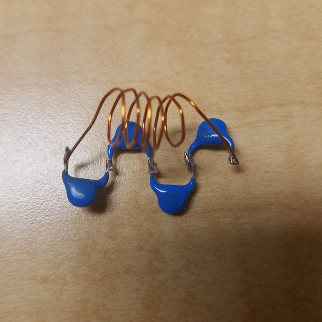
Homemade high voltage LC circuit. Ideally, when the capacitor bank is charged up, energy will oscillate between it and the crude inductor coil shown. This circuit should be able to handle upwards of 12 kV due to the capacitors being in series.
The hard part is, of course, the HV supply. With a source of high voltage arcs and a LC circuit, all that's left to do is hook everything up. I connected one lead of the HV stun gun to one end of the LC circuit, and connected an alligator clip wire to the oscillator portion to serve as a crude antenna. The second HV output lead is placed a few millimeters from the opposite end of the LC oscillator - this is the spark-gap.
I'd like to point out that spark-gap transmitters can't produce very high frequency radiation due to limitations in the LC part of the circuit. ARRL quotes this as 30 kHz to 30 MHz, which puts spark-gap transmitters out of reach of the FM and UHF/VHF ham radio bands. This unfortunately makes my regular transceiver useless at picking up EM waves from my spark-gap transmitter. But, the typical AM band lies around the 1 MHz mark, and works extremely well for this experiment, so I used my AM/FM radio to try and detect electromagnetic pulses produced by the transmitter.
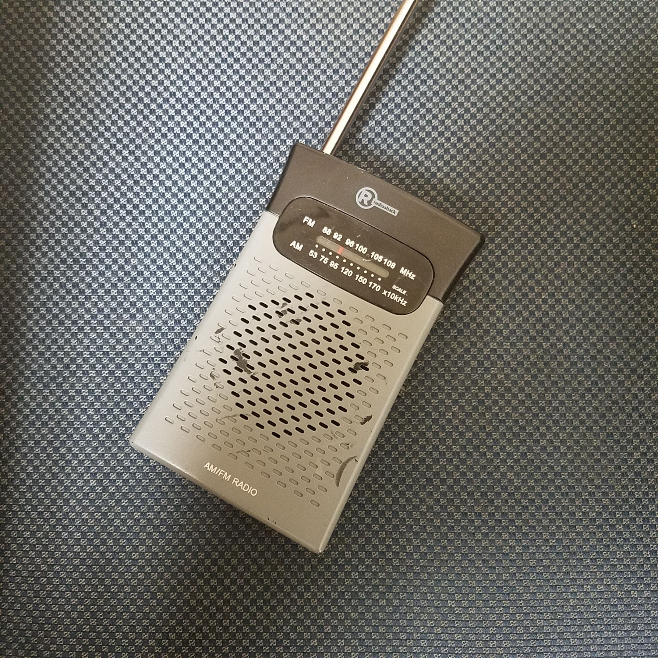
I used this radio to detect AM-band signals from the spark-gap transmitter. The long antenna helps pick up the extremely long ~1 MHz EM waves.
Anyway, all to do now is to fire up the circuit. This produces a small plasma arc (firing and closing several times per second) between the HV supply and the LC circuit. Here's an image of the transmitter in action, with the arc visible:
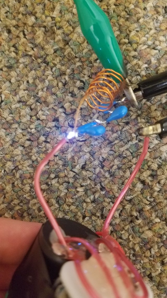
Spark-gap transmitter in action. Once again, the carpet is totally safe, as the fact that this high voltage is driven by a CW multiplier makes it extremely difficult to ignite things with it. The green clip leads to the "antenna", while the black clip leads back to the HV supply.
The results look good! Firing up the transmitter completely wipes out the radio receiver's ability to pick up a nearby AM radio station for at least 4-5 feet (my apartment is very good at blocking AM signals, so it was very difficult to test the transmitter much further than a few feet, as this required changing rooms which made it unclear whether the signals was being blocked by walls or the transmitter).
The signal is easily detected across the room, and likely farther away if I wasn't in this tiny room. Closer to the transmitter, you can actually hear the cracks of the spark-gap modulated into the signal on the radio receiver!
I did a few more tests to make sure the LC portion of the circuit was actually contributing in a meaningful way to the electromagnetic wave output. Without the green antenna wire, transmission range was negatively affected, as expected.
Notably, even without any extra circuitry or wires, the stand-alone stun gun actually jams the AM radio receiver within a few inches of the plasma arc. However, the amount of EM waves produced with just the stun gun is very low and the detectable range is very short. Adding on the extra oscillator circuitry as shown here turns it into a true spark-gap transmitter and massively boosts the range as my tests showed. If you don't have high voltage capacitors for the LC circuit and want to try this, you can also get decent results by just attached a long wire to one of the HV outputs and arcing to the other end, as it serves as a crude antenna.
Note that spark-gap transmitters are very wide-band: They transmit on many nearby frequencies, causing an interference nightmare. A high power spark-gap transmitter would get you in trouble with the FCC. I only transmitted for short periods of time in my already Faraday-cage like apartment so I doubt I caused any meaningful interference for my neighbors, especially on these low frequencies.
Press the button over and over again on the transmitter and you can send morse code over the air! But don't actually do this at long range, because in the US you'd break a bunch of laws due this being an unlicense wide-band transmitter.
If you're interested in reproducing this circuit for fun, here's the schematic of what I used. The dotted line indicates that everything inside is part of the black HV module.
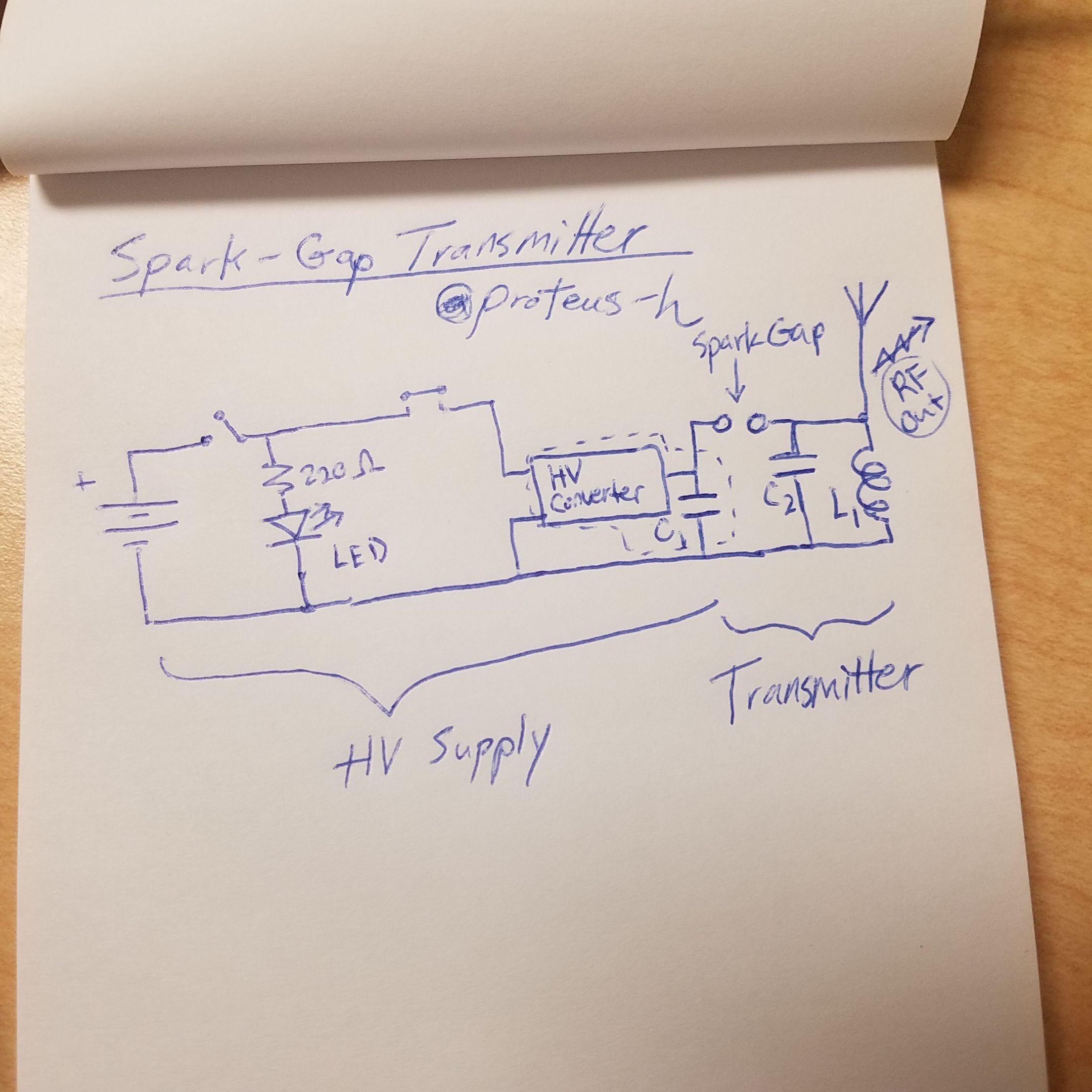
Schematic of this transmitter. C1 is the supply HV capacitor and is inside the black epoxy HV module. C2 is the four-capacitors-in-series capacitor you see above.
There are many ways to improve this design. The obvious one is to fix the antenna. The electromagnetic radiation produced here had a frequency of around 950 kHz as detected by my radio. This means that the wavelength of the wave was hundreds of meters long. The antenna I was using was a little over a foot long, so naturally a longer antenna would provide much more efficient production of electromagnetic waves.
Other improvements could include different LC circuits and a higher power high voltage supply.
I hope you learned something about early radio technology from this quick project. RF devices are often finicky to build but are pretty cool once you get them working. This is just about the most crude transmitter you can build, by the way, and essentially anything will be better suited for any purpose other than radio jamming (which isn't legal anyway). This was just a quick demonstration, but I might make it more permanent in the future with the help of a 3D printer.
If you have any comments, questions, or corrections, please let me know.
Thanks for reading!
Images not credited are my own. You are welcome to use them with credit.
Additional Sources
ARRL History of Spark-gap Transmitters
Spark-gap Transmitter Wikipedia Entry
Another great post @proteus-h. My father who worked as a radio technician at a Microwave link station remembers scaring apprentices when drawing a "talking" arc near the transmitter tower!