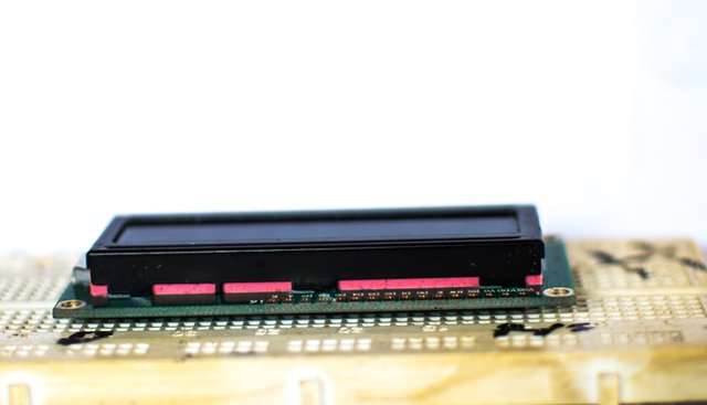
Interfacing LCDs with PIC microcontroller.
Hello guys it's really been a long time. Was busy with exams and I also wasn't well, so after my exams I had to take out time to rest and get myself. So yeah am back. Today I'm going to be talking on how you can interface your LCD with a pic microcontroller. We are also going to be using the mikro-c library.
What is an LCD?

LCD is an acronym that stands for liquid crystal display. It is a form of display used in electronics projects to display alphanumeric or graphical characters. They come in various shapes and sizes. Examples are 16×2, 40×2 etc. When we say 16×2 it means it can display 16 characters in two lines, while a 40×2 LCD can display 40 characters in 2 lines.
Types of LCDs
Based on the mode of connections to the microcontroller, they can be grouped into two categories;
1. Parallel display LCD
2. Serial display LCD
The parallel display LCD is the cheapest and hence the most commonly used LCD in microcontroller based projects. However, it consumes more pins from the microcontroller unlike the serial LCD which is though more expensive, but it does not use up most of the microcontroller pin.
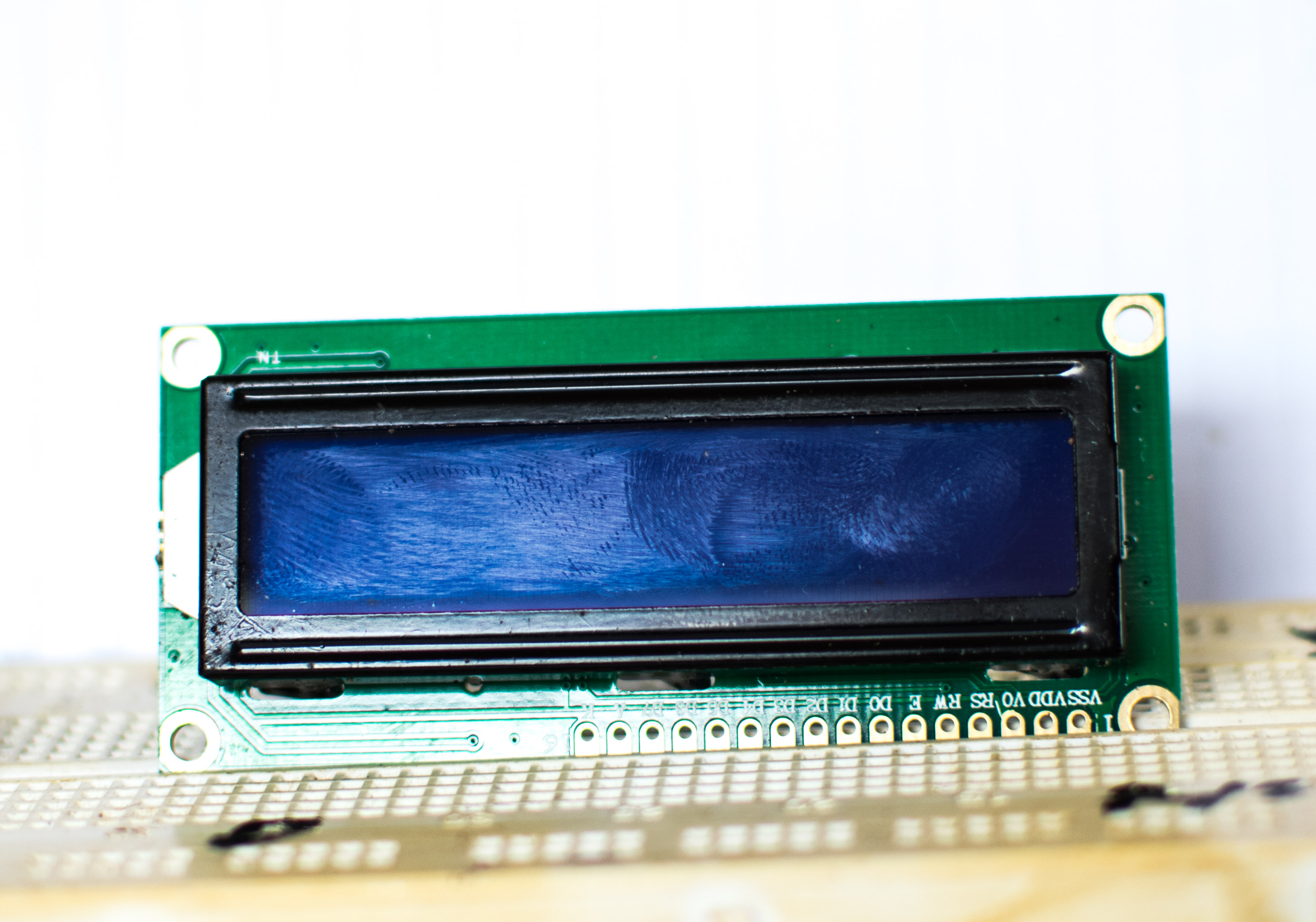
Identification of LCD pins and their functions

pin 1 is the VSS pin, that is the ground pin. This represents the negative terminal of the LCD. It is always connected to the negative terminal of the power supply unit.
pin 2 tagged as VDD is the voltage supply pin of the LCD. It is always connected to the positive terminal of the power supply unit.
Pin 3 is the contrast pin, it is represented as VEE. It is used to vary the contrast of the LCD. Hence for the contrast of the LCD to be varied this pin is connected to the middle pin of a variable resistor.
Pin 4 is known as the register select pin denoted as RS. When it is set to low, that is when it is connected to the lowest voltage terminals, the data pins of the LCD are interpreted as commands while when it is set to high the data pins are interpreted as data. Setting it to high means it is connected to a high voltage terminal.
Pin 5 is the read write pin (RW) . When it is connected to the lowest voltage source ( when it is set to logic 0), it means the that the LCD is in the write mode therefore data can be written from the microcontroller unit to the LCD. But when this pin is connected to a high voltage source , the LCD is said to be in the read mode therefore data can be read from the LCD to the microcontroller unit. However in majority of electronics projects and devices, data is usually written from the microcontroller unit to the LCD (this also helps to save more pins of the microcontroller.)
Pin 6 is the enabled pin (E). When this pin is set to high, the microcontroller will be able to access the LCD, but when it is set to low the microcontroller is denied access to the LCD.
Pin 7 to pin 14 (D0 -D7). These are the data pins of the LCD. They can be connected either in the 8-bit mode or in the 4-bit mode. In the 8-bit mode all of the pins are connected to the microcontroller unit, while in the 4-bit mode only pin 11 to pin 14 that are connected to the microcontroller unit.
MikroC pro library for pic microcontrollers
MikroC PRO provides a set of libraries that are compatible with PIC microcontrollers and their modules. They have various libraries such as the keyboard library, the ADC libraries etc. Am going to talk about the LCD libraries.
MikroC LCD libraries
The LCD libraries provided by mikroC pro is applicable only when the LCD is connected in 4-bit mode. Before using any of the libraries, the connections and directions of the LCD to the microcontroller must first be specified. If I am to connect the RS pin of the LCD to RB4 of the microcontroller all I have to do is write this line of code
sbit LCD_RS at RB4_bit// EXAMPLE OF THE NECESSARY CONNECTION AND DIRECTIONS OF LCD TO MCU.sbit LCD_RS at LATB5_bit;sbit LCD_EN at LATB4_bit;sbit LCD_D4 at LATB0_bit;sbit LCD_D5 at LATB1_bit;sbit LCD_D6 at LATB2_bit;sbit LCD_D7 at LATB3_bit;sbit LCD_RS_DIRECTION at TRISB5_bit;sbit LCD_EN_DIRECTION at TRISB4_bit;sbit LCD_D4_DIRECTION at TRISB0_bit;sbit LCD_D5_DIRECTION at TRISB1_bit;sbit LCD_D6_DIRECTION at TRISB2_bit;sbit LCD_D7_DIRECTION at TRISB3_bit;// END 0FF DIRECTION OF LCD TO MCUThere are 6 functions provided by mikroC pro to program LCDs they are :
1. Lcd_Init
2. Lcd_Out
3. Lcd_Out_Cp
4. Lcd_Chr
5. Lcd_Chr_Cp
6. Lcd_Cmd
Before any of this functions can be used, the LCD connections and directions must first be specified.
Lcd_Init function: is used to initialize the LCD module. It tells the microcontroller hey guy a LCD module has been connected to you.
Lcd_Out is used to printout text on the LCD, beginning from a specified position. Both strings and literals can be passed as text. Before this function can the used, the LCD must be initialized and also the directions and connections must be specified. So let's say I want to printout my name, all I have to do is to write this line of code
Lcd_Out(1,2,"fona");
what this code simply does is; it tell the LCD to write the word fona on row 1 column 2. To make this more fun you can replace my name with your name.
Lcd_Out_Cp is the pronounced as LCD out current position. What this function does is to printout out text on the current position of the cursor. To use this function, the connections and directions of the LCD module must be specified, secondly the LCD must be initialized.
Lcd_Chr it is read as LCD character. It is used to printout a single character on the LCD.
Lcd_Chr_Cp is used to printout a single character on the cursor's current position.
Lcd_Cmd this is pronounced LCD command. This function is used to call various commands. Such commands include to clear the screen of the LCD module, to turn off the cursor etc.
Conclusion
That's all guys, thanks for reading.
I am an embedded system designer and this article is as a result of my past experience and hence are my original works. The images are my own taken with my Nikon D5300 camera. You can check out my other articles here:
1. Building a digital thermometer.
2. Interfacing LEDs with PIC microcontrollers
3. Building a night lamp
Reference
Mikro elektronika support
MikroC libraries
LCD data sheet
Welcome back!
I do enjoy a good quality article about electronics.
I really envy your free time as you can get to play with those.
I am still involved in decorative paining on my house so what I do is still on the macro level.
How did the exams go? Can we be proud of you? :)
Update: You could format the text a little more. Break it into readable chunks and segment it a little. Start the sentences with capital letter, capitalize the first letter of the headings.
It sells your content better, because the content is good.
Thanks for the kind words. Oh that's nice will put up some posts soon on led matrix and led cubes, but am been held back due to the fact that some of the components I ordered for haven't arrived yet. Lol the exams started well, but then I fell ill during that period so missed some papers. But it general I will say it was good.
Thanks for the advice it has been amended.