Building A Night Lamp (day and night detector)
Hello steemians! Hope you had a lovely week. Today we are going to be building an automated night lamp. Yeah it may sound completely difficult, but trust me this post is meant to help anyone who has zero knowledge about electronics build it.
Brief description of the night lamp.
The night lamp is a system made up of a light dependent resistor as the main component of the system. The night lamp will be able to come on at night, and when the day is bright it goes off. One does not need to interfere in the operation of the system. How cool can that be! The circuit is going to have a calculated delay to respond to signals. This is done in other to avoid false scenario such has; someone pointing an artificial light source on it, a shadow been cast on the circuit during the day. For this circuit we are going to be using a led has an output signal indicator.
component needed
In other to build this circuit, we are going to be using the following components:Bread board.
Jumper wire.
A power supply.
NE 555 timer IC.
Light Dependent Resistor (LDR).
light Emitting Diode (LED).
10k resistor.
NOT gate IC.
47k resistor.
0.01uf capacitor.
47uf capacitor.
47 ohm resistor.
Brief description of components

BREAD BOARD.
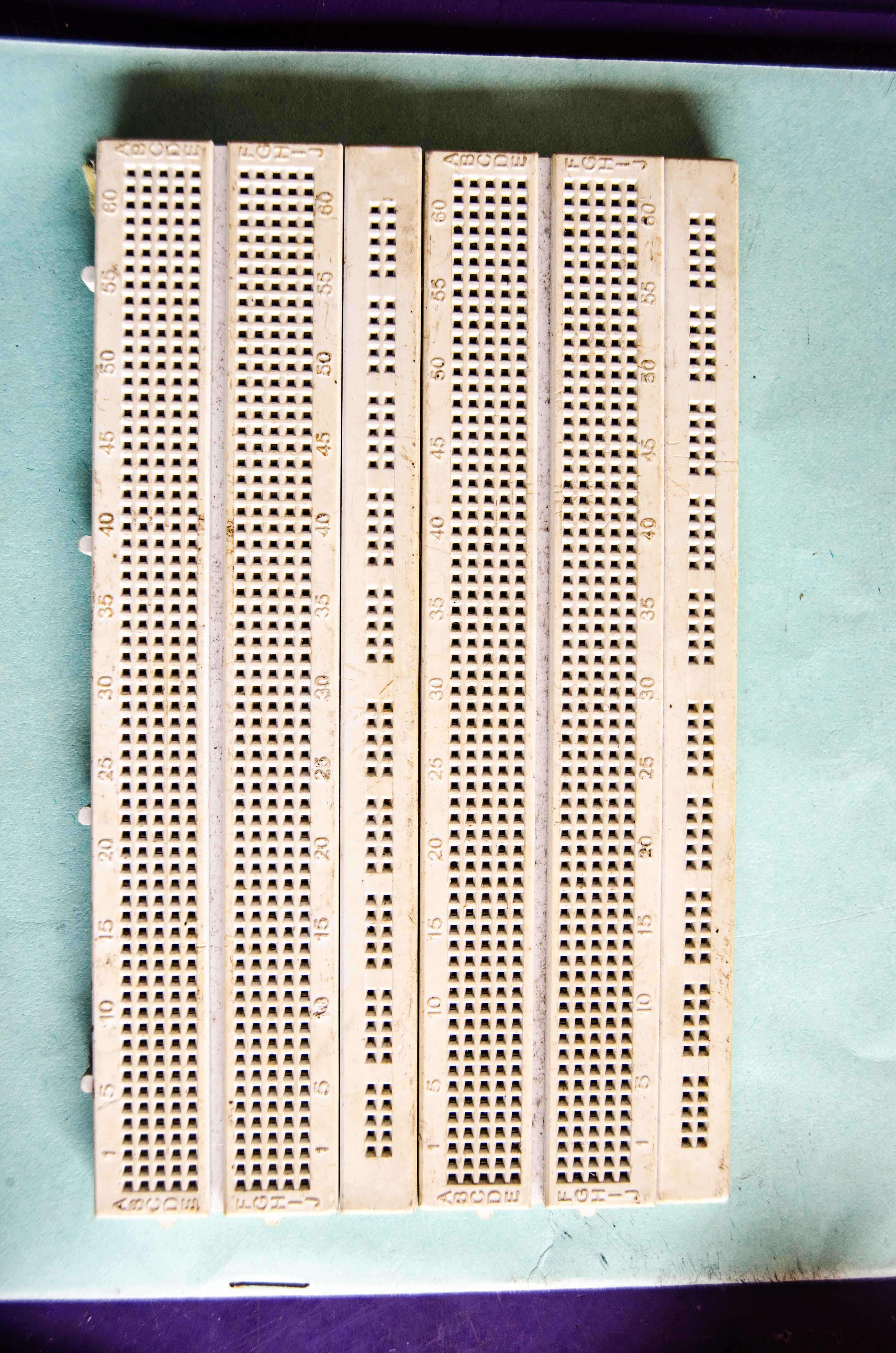
A bread board is a solderless electronic board used to build temporary circuits that doesn't require soldering. It is mainly used to experiment circuits, before the are moved to a vero board or printed circuit board (PCB) for soldering. It is made up of vertical and horizontal dotted roles and column.
JUMPER WIRE.
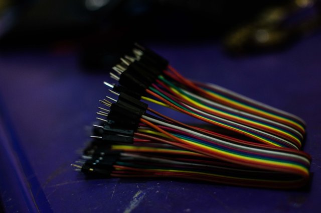
Just like the name implies, a jumper wire is used to connect one or more components that are far from each other. Networking cables can also serve this purpose.
POWER SUPPLY.
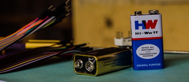
A power supply unit is the source of power or voltage for our circuit. If you don't have a power supply unit, no worries. You can make use of a 9 volt battery.
NE 555 TIMER IC.
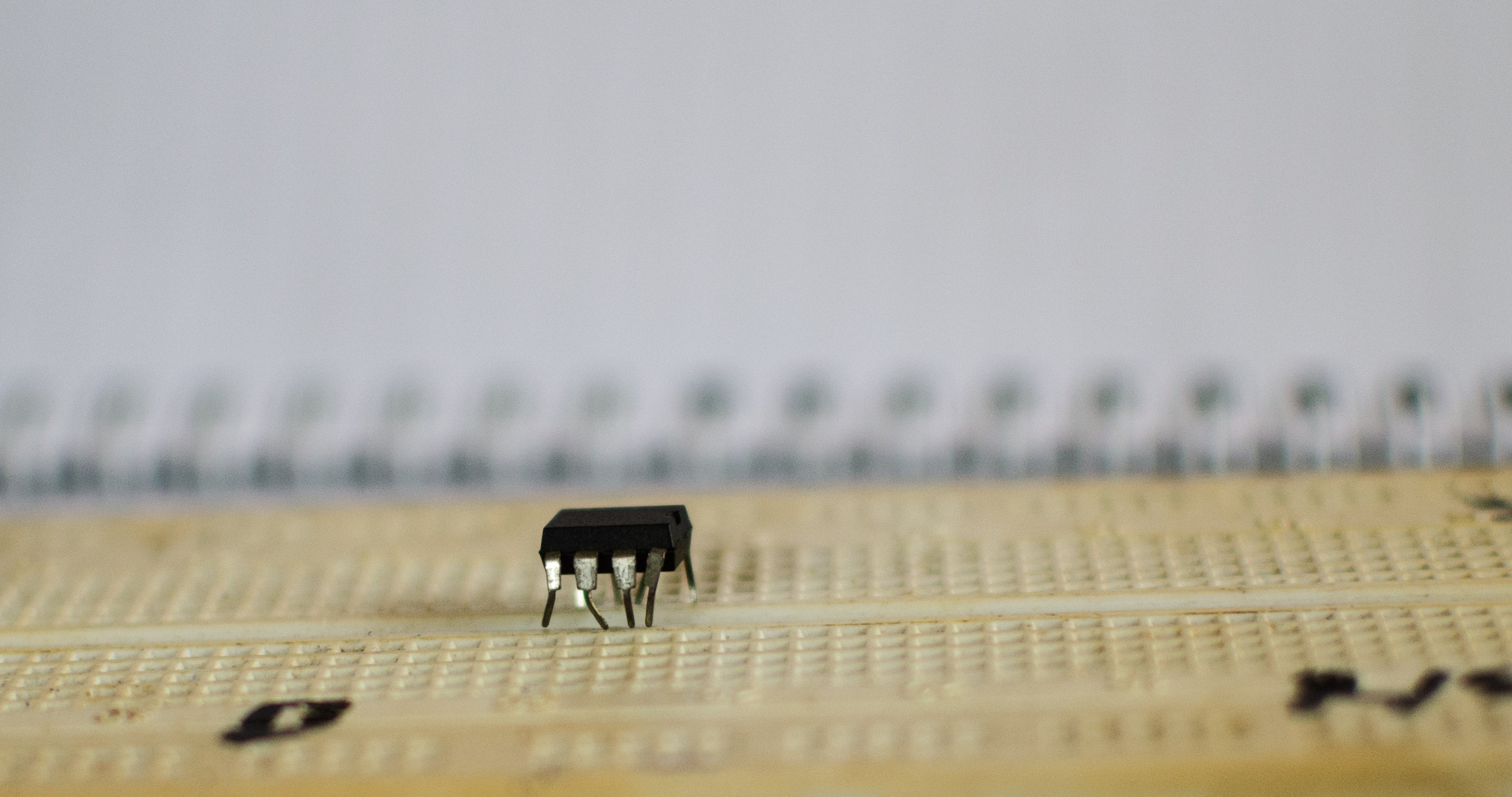
The 555 timer IC is the world's most popular IC. It is used to create timing in electronics circuit. In our night light circuit, the 555 timer is what helps is delay the response to signals, by operating it in the mono stable mode. The 555 timer IC has three modes of operation namely: The astable mode. The mono stable mode. The bistable mode.
LIGHT DEPENDENT RESISTOR (LDR)
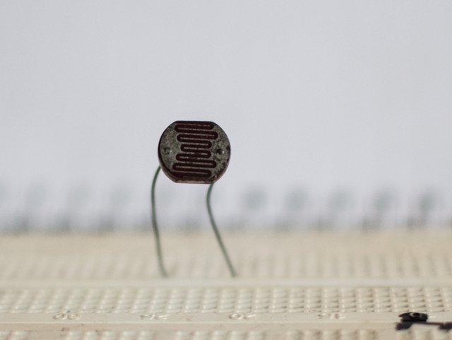
The light dependent resistor is a type of resistor also know as photo resistor whose working principle is based on photo conductance that is, it's resistance depends on light. The surface of the LDR contains a photo sensitive material. In the presence of light, it has a low resistance. But when it is placed in the dark, it's resistance is high. The data sheet says nearly 1M ohms. LDR usually come in various sizes, ranging from 3mm-5mm
LIGHT EMITTING DIODE (LED)
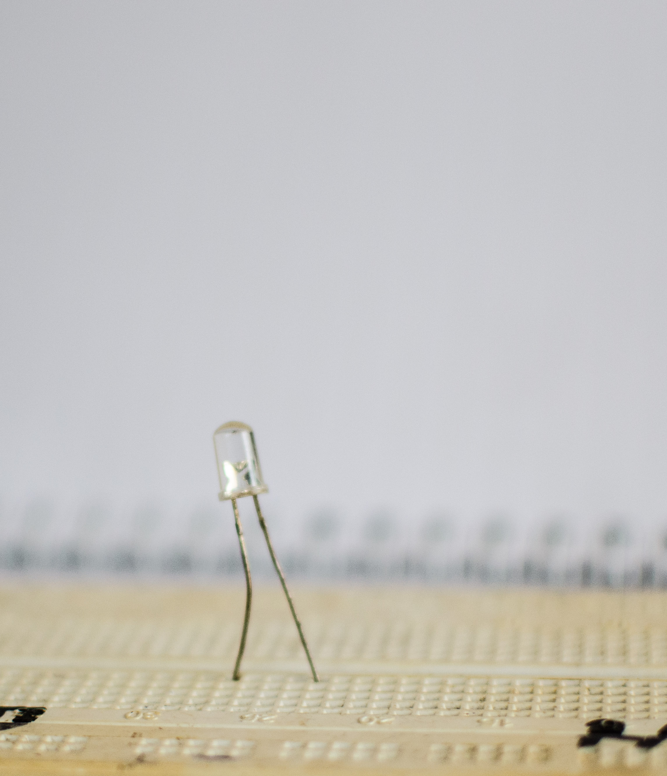
A light emitting diode is a type of diode which when forward biased, emits light. In this circuit, it is going to be used has our output signal indicator. It has polarity. The longest pin is usually the positive pin, while the negative pin is the shortest pin. If it is an old LED and the pins are equal in length, the only way to know the polarity is buy using a multi meter. Turn the knob of the multi meter to continue and use the probe of the meter to touch the pins of the LED. If the led comes on, the polarity of the probe on the pin is has the same polarity as the LED. If it doesn't come on, the LED is bad.
NOT GATE IC.
A NOT gate IC also know as an inverter, is a 14 pin logic IC with part number 7404. It has six inverter inside of it. A not gat IC gives a compliment of it's input as it's output. That is if the input I'd high, the put will be low. And if the input is low, the output will be high. Pin 1,3,5,9,11 and 13 are all input pins, while pin 2,4,6,8,10,12 are the output pins. Pin 14 is the supply voltage pin and pin 7 is the ground of the logic IC.RESISTOR
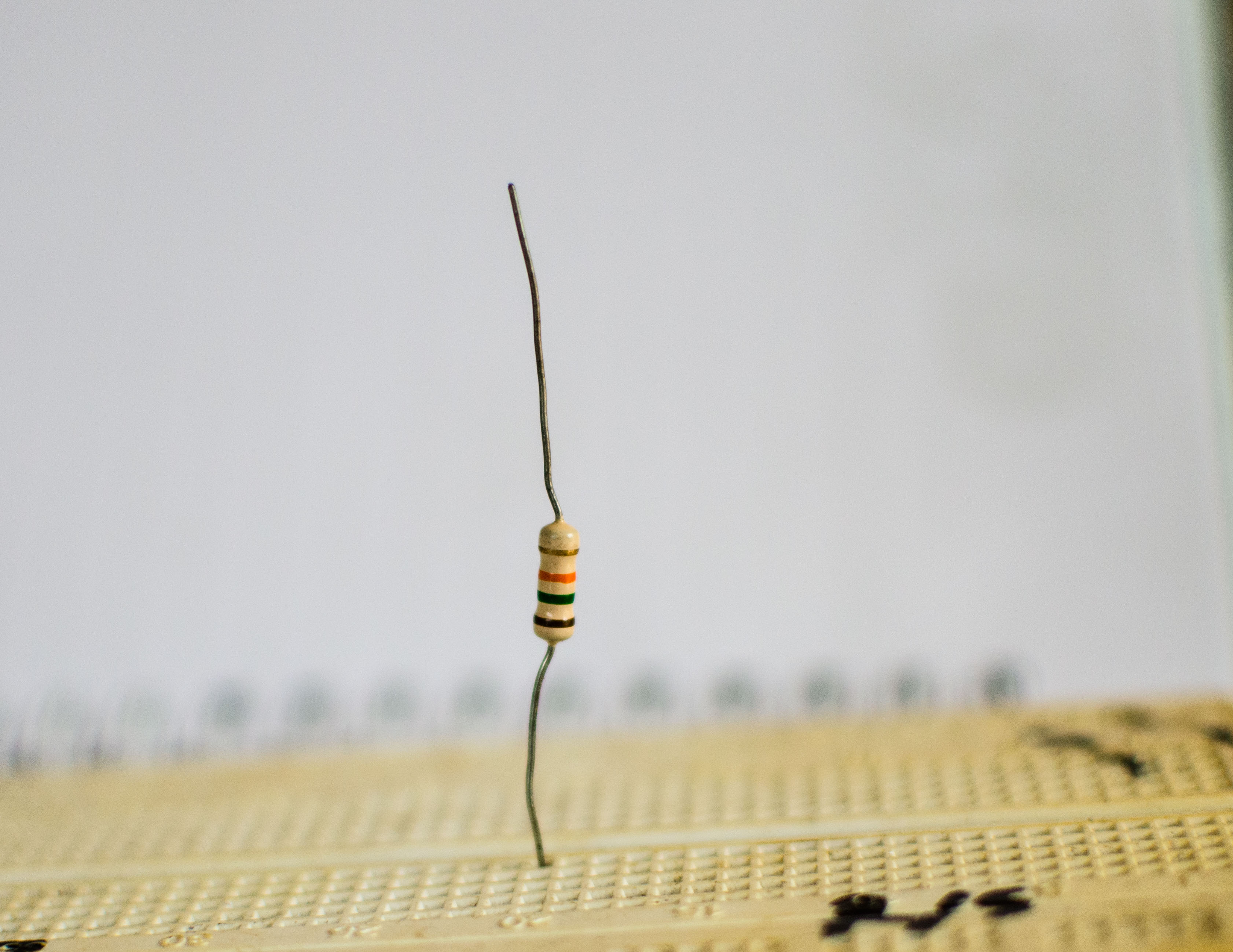
A resistor is an electrical device, used to limit the amount of current flowing in a circuit. Depending on the way they are combined, the can act has a voltage divider network, or has a current divider network. In our circuit, the 10k resistor and the LDR are acting has a voltage divider. Recall that we earlier stated that LDR is a type of resistor. When resistors are connected in series they act has a voltage divider network. Hence the 10k resistor and the LDR are connected in series. There are three types of resistors; The fixed resistor. The variable resistor. The photo resistor. For the fixed resistors, they have a fixed resistance and their resistance are denoted using colour coding. The fixed resistor has a knob on top of it, which is used to vary it's resistance. The maximum resistance it can give is usually written on the knob of the resistor.
CAPACITOR.
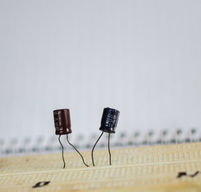
A capacitor is an two terminal electrical device used to store electrical energy in the form of charges. It consists of two conductors separated by a dielectric (an insulator). When a capacitor and a resistor are combined together, they create a timing in the circuit. In our circuit, R2, R3 and C2 are connected in other to create a timing in the circuit. It should be noted that capacitors have polarity. The longest terminal is usually the positive terminal while the shortest terminal is the negative terminal. However, if the terminals are of equal length, the negative terminal is denoted with a subtraction sign beside it. Connection of the components and how the circuit works
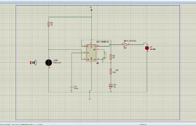
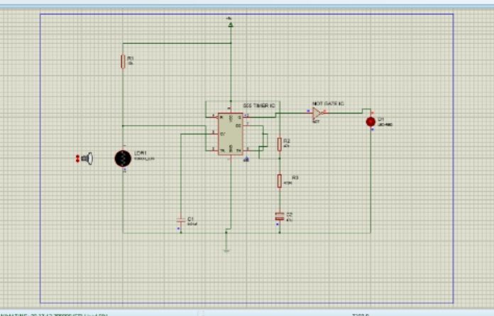
The success of this depends on how well we connect our LDR and 555 timer IC. Majority of the components are connected to the 555 timer IC and has such, we are going to start our connection from our 555 timer IC. Pin 8 and 4 which is the power and reset pin respectively, are connected together. Pin 5 is the control pin. It is connected to pin 1 which is the ground of the IC, via a 0.01uf capacitor. Pin 3 is the output pin of the 555 IC and is connected to any of the input pin of the NOT gate IC. The output of the NOT gate is connected to the positive terminal of the LED, while the negative terminal of the LED is connected to pin 1. The 10k resistor (R1) is connected to the LDR in series as a voltage divider network. Pin 2 which is the trigger of the 555 timer is connected to the junction between the 10k resistor and the LDR. Pin 7 and 6 which are the discharge and threshold pins respectively, are connected together, and then connected between R2 and R3. R3 is then connected to the positive terminal of C2. The negative terminal of C2 is connected to pin 1 of the 555 timer ic. R2, R3 and C2 creates the delay for our night lamp. In other to calculate the time delay, the formula; T= 1.1×(R2+R3)×C2. Remember we stayed earlier on that the success of this circuit is dependent on the LDR and the 555 timer IC. The LDR and the 10k resistor (R1) are connected as voltage divider using the formula; Vin×LDR/R1+R2 so that the pin 2 of the 555 timer IC can be supplied with 2/3 of the supplied voltage. Where Vin is the voltage supplied by our power supply unit. Below is a simulation of the circuit showing you how it is going to be like.
All images where taken with a Nikon D5300 and edited with light room software. If you have any questions, feel free to use the comment section.
Impressive. I knew most of it since I am also a computer programmer and steemstem writer. I followed you and I will vote your articles once I recover my VP. I will propose your links to further Curie and Qurator promotion.
Thank you very much, I would really appreciate that :)
Being A SteemStem Member
Very cool! I used to build Radio Shack kits when I was a youngster but I never really understood how they worked.