COEFFICIENT OF OPTIC ABSORPTION. PART 3. (TRANSMISSION AND REFLECTIVITY)
Hello friends of Steemit, here I present the third part of the coefficient of optical absorption, where transmission and reflectivity will be discussed.
If you have not seen the first and the second part, I invite you to see them here:
Reflection and transmission of an incident beam.
The transmission coefficient (T) is defined as the ratio between the intensity transmitted with the incident intensity,  . If the sample has a thickness x, an absorption coefficient
  and a reflectivity R, the radiation passing through the first interface is
  , the radiation reaching the second interface is
  , and only a fraction
  emerges. The internally reflected portion managed to emerge eventually, but considerably attenuated.
These multiple internal reflections are illustrated in the following figure:

Energy flow in a system that allows multiple internal reflections.
Then, the transmission is given by:
 eq. (1)
When the product  is large, the second term in the denominator can be neglected to obtain:
 eq. (2)
If R is not known for a given material, the tramittance of two samples with different thicknesses,  , can be measured. You can get
  from the following relationship:
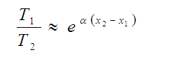 eq. (3)
Since  , it is not necessary to know
  to use Equation (3), where
  can be replaced by
If R and x are known, Equation (2) can be used to obtain :
 eq. (4)
To use this last equation it is important to mention two experimental details:
First, the spectra must not present any type of absorption for energies less than Eg. If this apparent absorption exists, it is usually due to superficial problems of the sample, and can be eliminated by normalizing the transmission with that which the sample can have under ideal conditions, that is, when the only loss is due to the change of medium when entering and leaving, the light of the sample. This ideal transmission is  . Therefore, the normalizing parameter of the transmission is:
 eq. (5)
Where the value of the maximum transmission is obtained for each sample of its transmission spectrum.
The second experimental detail is that of parasitic light, which is not always possible to eliminate when performing the measurement. To perform the correction, the minimum transmission (Tmin) that appears for energy values above Eg must be subtracted from the total transmission.
With these corrections Equation (4) changes to:
 eq.(6)
REFLECTIVITY
From the Fresnel equations we have that for any homogeneous, isotropic and linear medium, the amplitude of the reflection coefficients are given by:
 eq. (7)
For the case in which the electric field is perpendicular to the plane of incidence:
 eq. (8)
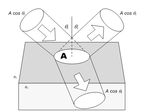
The following figure shows the case where the electric field is parallel to the plane of incidence; where ni and nt are the incident and transmitted refractive indices respectively, θi and θt are the incidence and transmission angles, |Er| is the amplitude of the electric field of the reflected beam and |Ei| is the magnitude of the electric field of the incident beam.
Reflection and transmission of an incident beam.
Then, when θi = 0 (and consequently θt = 0) we get:
 eq. (9)
Reflectance is the ratio between the reflected and incident flow:
 eq. (10)
since the incident waves and the reflected waves are in the same medium, that is,  we have:
 eq. (11)
Using the form of components, we have:
 eq. (12)
When  the plane of incidence is undefined and there is no distinction between the parallel and perpendicular components of R, so when combining equations (9), (11) and (12) we obtain:
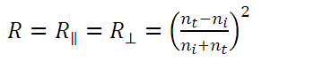 eq. (13)
In the case of the normal incidence of a beam of light on a metal surface, it is necessary to rewrite the equations because the metals have a complex refractive index  if we also assume that the wave is initially in the air
  , we have from equation (9) that:
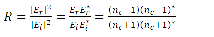 eq. (14)
finally obtaining:
 eq. (15)
Where n and k are the actual refractive index and the extinction coefficient of the material, respectively. Most authors use k to denote both the wave vector and the extinction coefficient, so we must be careful not to confuse them.
REFERENCES:
Pankove J, (1971),Optical Processes in Semiconductors, New York,Dover Publications.
Hecht E, Zajac A, (1977),Óptica, Fondo Educativo Interamericano.
Díaz R, Merino J. M., Martín T, Rueda F, León M,(1998),An approach to the energygap determination from the reflectance measurements.
McKelvey J. P, (1993),Física del Estado Solido y de Semiconductores, 1º Edición,Mexico, Editorial Limusa.
D.B Gadkari, K. B Lal y B M Arora. (1999). Growth of undoped and Te doped InSb crystals by vertical directional solidification technique, Indian Academy of Sciences.
FurdynaJ.K, (1988), Diluted magnetic semiconductors, Journal of Applied Physcs, Vol 64, Nº 4.
Parker Sybil P, (1991), DicionarioMcGraw-Hill de Física, Tomo I, México,McGraw-Hill.
