Introduction to Mobile Networks - GSM CS Attachment

source: pixabay
In this series' previous post, Introduction to Mobile Networks, we learned about the concept of Circuit-Switched (CS) services and the associated GSM network architecture. The reader was also introduced to the basics of GSM radio resource management and how a UE can be assigned a dedicated logical channel in order to initiate an application procedure, such as sending an SMS or placing a voice call.
In this post I will explain the most fundamental procedure which must takes place before the subscriber can have access to other services - the attachment procedure.
Cells and Location Areas
In the 2G and 3G mobile networks the radio coverage is divided into zones referred to as location areas. Each location area is identified by a unique location area identity (LAID) which consists of:
- The operator PLMN identity (combined MCC/MNC), and
- A location area code (LAC).
The LAC is a number between 0 and 65,535 (2 octets) which must be unique within a single operator's network.
Each location area is in turn covered by one or more cells. A cell is uniquely identified within a location area by a cell identity (CI), another value ranging between 0 and 65,535.
From this we can deduce that a single location area may be covered by many cells.
A cell can be uniquely identified across all operators by its cell global identity (CGI), which consists of:
- The LAI (PLMN ID + LAC) within which the cell radiates, and
- The cell identity
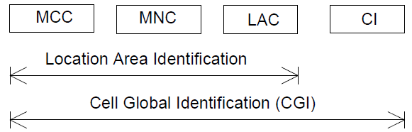
source: 3gPP 23.003
It should be noted that, according to the standards, only the VLR managing a subscriber is known in the Home Location Register (HLR), not the location area nor the cell identity.
The exact location area to which a subscriber is attached is known by the serving Visitor Location Register (VLR).
Let's recap the hierarchy of network elements in the GSM CS network architecture:
- A cell, identified by a CGI, is a single zone of transmission in the network associated with one or more transceivers (TRXs) .
- A BTS manages one or more TRXs and therefore one or more cells.
- A BSC manages the radio resources of one or more BTSs.
- An MSC is the main switching function for calls and short text messages (SMSs).
- A VLR stores the subscriber information required to provide service to that subscriber through the associated MSC.
The above relationships is depicted in the following diagram.
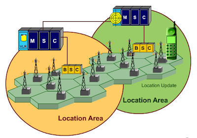
source: Jelly Telecommunications and Technologies
The most common cell deployment is for each cell to cover a 120° area thus, in this configuration, it takes three cells to cover a full 360° coverage. Schematically, the transceivers (radio heads) transmitting the cells reside on the hexagon vertices as shown below.
source: U.S. Patent 4,144,411
The following shows a photograph of a typical TRX radio head configuration on a radio mast.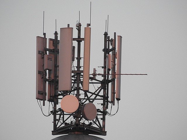
source: pixabay
A Note on the Use of Temporary Identity
In previous posts we saw that each subscriber in the network is identified by a permanent identity called IMSI.
This information is considered sensitive. If the IMSI is frequently sent in the clear over the radio there is a chance that an attacker could tap the traffic from a specific subscriber and/or attempt to impersonate that subscriber anywhere in the network.
For this reason the standards define mechanisms whereby the subscriber can be assigned a temporary identity called Temporary Mobile Subscriber Identity (TMSI) while attaching to a VLR.
The TMSI is a unique 4 octet value allocated by the VLR to identify the subscriber which must be used by the UE to identify itself at the start of every procedure, instead of the IMSI. Internally the VLR maintains a mapping table of all TMSI / IMSI assignments.
At anytime the VLR can assign a new TMSI but this is usually done during the location update procedure.
The Location Update Procedure
When a UE is turned on it must first find the best GSM cell and attach to the network through a series of steps called the location update procedure.
This procedure also happens when:
- The UE moves to another location area.
- The UE has been inactive (no call, SMS, etc.) for a specific amount of time. This periodic location update procedure provides a way for the VLR to know when a UE has become unreachable, for example when the UE is out of battery.
The main objectives of the location update procedure are as follows:
- Register the subscriber within the local VLR.
- Notify the network about the current location area used by the subscriber.
- Authenticate the subscriber and secure the communication between the UE and the network.
- Notify the HLR of the VLR with the current subscriber registration.
- Provision the VLR with key subscription data from the HLR.
- Assign a new TMSI (see previous section).
The VLR is a key network element which stores all the information about the attached subscriber that is required to provide CS services to the UEs.
Turning on the UE
The following sequence diagram illustrates the procedure happening when a UE is turned on for the first time. As a refresher for the previous post I will also show in the procedure how the required radio logical channels are used in the procedure.
source: original illustration
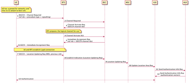
When the UE is powered on it tries to select the best cell. This will be described in further details in a future post. The UE then initiates the location update procedure as follows:
- UE sends a Channel Required on the RACCH and specifies that it needs a channel for the purpose of signalling. It specifies a reference number for this request.
- BTS forwards the Channel Required to the BSC
- BSC finds a free SDCCH for the procedure (SDCCHs can be used for signalling), and requests the BTS to activate that channel by sending a Channel Activation Request along with the desired channel number of the SDCCH.
- The BTS prepares the SDCCH for use and sends back a Channel Activation Acknowledgement.
- The BSC now instructs the UE to use this SDCCH by sending an Immediate Assignment Command to the BTS. The message includes the same reference number as in the Channel Required.
- The BTS forwards the Immediate Assignment Request message over the AGCH broadcast channel. Upon receiving the Immediate Assignment Request with the same reference number, the UE initiates a Lap.d connection with the BTS for reliable transmission of messages over the SDCCH.
- The UE now sends a Location Updating Request over the SDCCH. The message contains the IMSI of the subscriber along with other information such as the identity of the previously attached location area.
- The BTS forwards the Location Updating Request to the BSC within an Establish Indication message.
- The BSC forwards the Location Updating Request to the MSC.
- The MSC requests its local VLR to update the location of the subscriber.
- At this stage the VLR normally wants to authenticate the subscriber. To do so, it needs to request the home network for authentication information. It does so by sending a Send Authentication Info Request message to the subscriber HLR.
- The HLR responds with authentication information in a Send Authentication Info Response.
- The VLR iniates an authentication procedure with the UE. This procedure will be further explained in a future post.
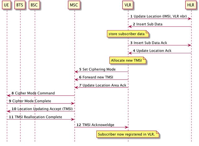
The subscriber using the UE is now fully authenticated with the network. The VLR may now continue the location update procedure as follows:
source: original illustration
- The VLR sends an Update Location message to the HLR. This message contains the IMSI and the ISDN number of the VLR itself.
- Upon verifying that the IMSI is a valid subscriber, the HLR transfers all relevant subscriber data to the VLR by sending an Insert Subscriber Data Request. The subscriber data includes various information such as a list of allowed services (e.g. originated/terminated calls, SMSs), unconditional forwarding numbers (if any), cells that are barred for this subscriber, etc.
- The VLR stores the subscriber data and returns an Insert Subscriber Data Acknowledgement to the HLR.
- The HLR sends an Update Location Acknowledgement to the VLR.
- In most circumstances the VLR now allocates a new TMSI for the subscriber. It also instructs the MSC to start ciphering (encrypting) traffic on the radio interface by sending a Set Ciphering Mode message.
- It also indicates the new TMSI to the MSC by sending a Forward New TMSI message.
- Finally the VLR sends an Update Location Area acknowledgement to the MSC. From this point on the subscriber is fully registered in the VLR
- The MSC now proceeds on activating ciphering on the radio interface. To do so it sends a Ciphering Mode Command to the UE. This message includes the ciphering key to use. (Note for simplicity the diagram does not show each individual message transfer between the MSC and the UE: BSC and BTS)
- Once the UE has prepared ciphering it sends back a Ciphering Mode Complete to the MSC. From then on all traffic is encrypted between the UE and the BTS (but not between the BTS and the MSC)
- The MSC sends a Location Updating Accept to the UE. The message includes the new TMSI to be used by the UE.
- The UE stores the TMSI for later use and sends back a TMSI Reallocation Complete to the MSC.
- The MSC sends a TMSI Acknoweldgement to the VLR. This tells the VLR that the TMSI was successfully assigned.
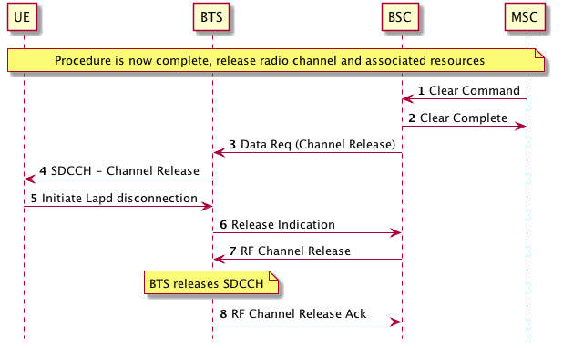
The location update is now complete. All that remains is for the MSC to release the radio channel (SDCCH) used by the UE and all associated resources:
source: original illustration
- The MSC sends a Clear Command to the BSC.
- The BSC sends back a Clear Complete to the MSC
- The BSC Sends a Channel Release to the BTS (in a Data Request).
- The BTS forwards the Channel Release to the UE over the SDCCH.
- The UE initiates a Lapd disconnection.
- The BTS indicates the layer 2 disconnection to the BSC by sending a Release Indication message.
- The BSC now instructs the BTS to deactivate the SDCCH by sending an RF Channel Release message.
- The BTS releases the channel and sends back an RF Channel Release Acknowledgement to the BSC.
After this procedure the LAI of the serving cell and the TMSI are now stored in the UE and the VLR. The ISDN number of the serving VLR is stored in the HLR.
The location of the subscriber is required for the UE to be reachable for incoming calls, SMSs, etc.
Location Update with VLR Update
Recall that a VLR manages several BSCs/BTSs and therefore covers several location areas.
What happens when a UE moves to a location area that is managed by a different VLR? Three things need to be taken care of:
- The new VLR must fetch the subsriber context (including subscriber data) from the old VLR.
- The HLR must be notified of the new VLR ISDN number.
- The old VLR must be notified that the subscriber has moved to a new VLR.
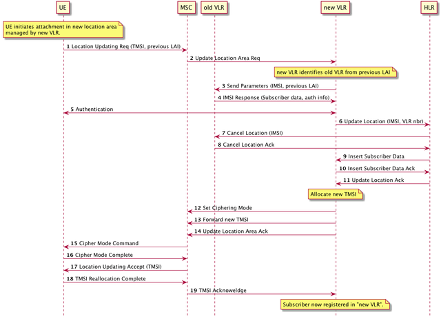
The following diagram illustrates how the above is achieved.
source: original illustration
- UE sends Location Updating Request to MSC, as in previous section (few steps are not shown here). It specifies its current TMSI allocated in the old VLR and the LAI of the location area it comes from.
- MSC sends Update Location Request to new VLR
- New VLR identifies old VLR from the specified previous location area LAI. It sends a Send Parameters message to the old VLR to request the subscriber context. This message must include the TMSI and the previous location area.
- The old VLR identifies the subscriber context and sends it back to the new VLR in an IMSI Response message. This message may include authentication information.
- The new VLR may initiate the authentication procedure with the UE.
- The new VLR sends an Update Location to the HLR with its own ISDN number.
- The HLR updates its record for the subscriber and sends a Cancel Location to the old VLR (as it had stored previously the old VLR ISDN number).
- The old VLR deletes the subscriber context and sends back a Cancel Location Acknowledgement.
- The HLR transfer new subscriber data to the new VLR by sending a Insert Subscriber Data message
- The new VLR stores the subscriber data and sends an Insert Subscriber Data Acknowledgement back to the HLR.
- The HLR accepts the update location with an Update Location Acknowledgement.
- The new VLR allocates a new TMSI and requests ciphering of traffic sent on the radio interface by sending a Set Ciphering Mode message to the MSC.
- The new VLR notifies the MSC of the new TMSI
- The new VLR accepts the location update.
- The MSC requests ciphering by sending a Cipher Mode Command to the UE
- The UE replies with a Cipher Mode Complete
- The MSC sends to the UE an Location Updating Accept with the new TMSI.
- The UE responds with a TSMI Reallocation Complete
- The MSC sends a TMSI Acknowledgement to the VLR.
The subscriber is now fully registered in the new VLR and cleared from the old VLR.
What Next?
We have now an understanding of the signalling involved in registering a UE within a VLR and notify in the process its location to the network.
In the next post we will examine in details the subscriber is authenticated with the network and how the authentication procedure is used to derive the security keys required to security and integrity check all messages transferred between the UE and the network.
Acronyms and Concepts
| Acronym | Meaning | Description |
|---|---|---|
| AGCH | Access Grant Channel | A type of downlink broadcast channel used by the network to indicate to the UE if a channel has been assigned or not. |
| BSC | Base Station Controller | The network element in charge of managing and assigning radio resouces to the BTS and the UEs (i.e., the "orchestrator" of radio resources). |
| BTS | Base Transceiver Station | The element residing in the operator's network providing radio transmission between GSM UEs and the network |
| CI | Cell Identity | 2 octet value identifying a cell within a location area |
| CS | Circuit-Switched | Virtual connection with fixed allocated network resources |
| HLR | Home Location Register | Stores all subscriber information such as IMSI, access and service rights, location information, etc. |
| MSC | Mobile Switching Centre | Responsible for servicing all CS application procedures (mobility, messaging, voice calls, etc), switching calls with external telephony networks and forwarding SMSs to Short Message Service Centres (SM-SC) |
| LAC | Location Area Code | 2 octet value identifying one location area within an operator's network |
| LAI | Location Area Identity | Concatenation of PLMN Identity and LAC, uniquely identifying a single location area across all operators |
| SDCCH | Stand-alone Dedicated Control Channel | A type of logical channel used for signalling traffic |
| TMSI | Temporary Mobile Subscriber Identity | A temporary subscriber identity assigned by a VLR to prevent exchange of the permanent subscriber identity (IMSI) through the network |
| TRX | Transceiver | Radio receiver / transmitter |
| UE | User Equipment | Terminal used by the subscriber to access the mobile network, such as smartphone, modem, IoT device, etc. |
| VLR | Visitor Location Register | Stores key information about all subscribers attached the the group of cells that it manages. |
| Concept | Description |
|---|---|
| Downlink | Network to UE direction |
| Location Area | Area of radio coverage within an operator's network |
| Uplink | UE to Network direction |
Reference
- GSM Network Architecture (3GPP TS 23.002)
- Mobile radio in interface layer 3 specification; Radio Resource Control (RRC) protocol (3GPP TS 44.018 version 13.0.0 Release 13)
- Location management procedures (3GPP TS 23.012)
- Mobile Application Part (MAP) specification (3GPP TS 29.002)
Previous Posts in this Series
Introduction to Mobile Networks
Introduction to Mobile Networks - The GSM CS Architecture
As always do not hesitate to leave comments with your questions and I will make sure to reply with the best possible answers.
Being A SteemStem Member
Congratulations! This post has been upvoted from the communal account, @minnowsupport, by irelandscape from the Minnow Support Project. It's a witness project run by aggroed, ausbitbank, teamsteem, theprophet0, someguy123, neoxian, followbtcnews, and netuoso. The goal is to help Steemit grow by supporting Minnows. Please find us at the Peace, Abundance, and Liberty Network (PALnet) Discord Channel. It's a completely public and open space to all members of the Steemit community who voluntarily choose to be there.
If you would like to delegate to the Minnow Support Project you can do so by clicking on the following links: 50SP, 100SP, 250SP, 500SP, 1000SP, 5000SP.
Be sure to leave at least 50SP undelegated on your account.