CAM - Computer Aided Manufacturing - University Project PART 2 - CATIA V5 Student Edition (ENG/ITA)
ENG
Introduction to the 2nd part
In this second part of the project related to the CAM (Computer Aided Manufacturing) course, we will discuss the topics concerning Machining Features and Setup Definition.
If you haven’t had the pleasure of reading the first part, I invite you to take a look here, where you will find the introduction to the project and the selection of tools.
Enjoy the reading
Machining features identification
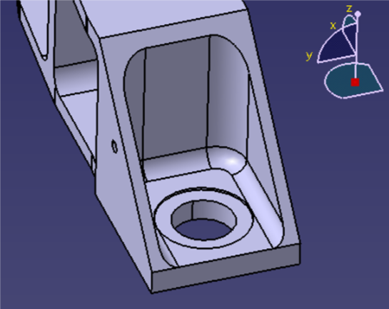
In order to create the final part, a number of features have been performed: face milling, profile contouring, drilling and pocketing.
Pockets

Our workpiece contains five pockets located on one side and other two at the extremities of the part. For creating each pocket we proceeded as follow: first of all by means of a drill we performed some holes whose allowed us to remove a huge amount of material; one hole was enough for the pockets at the extremities and for the two 60x60mm on the side, while for the 85x60mm two holes (and for the 140x60mm three holes) could be made to maximize the amount of chip removed. Then we performed a profile milling with an endmill for roughing the sides and finish the bottoms of the pockets: to this means we choose a 6,35mm radius tool which enabled us to create toolpath closer to the sides. The last step was then the borders’ finishing, which has been performed with a 6mm head radius end mill.
Edge fillet

Furthermore, on the pockets bottom the part has a 6mm edge fillet, which has been machined in the last finishing step with a 6mm head radius end mill.
Profile contouring & Face milling

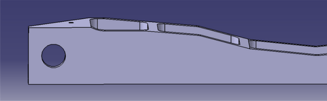
For obtaining the desired shape of the front profile and of the extremities, we have performed several profile contouring operations. The front profile has been roughed with a 25mm end mill, which is very fast due to the small radius engagement but couldn’t be used to finish the surface because it’s too big for obtaining the 12mm radius curve in the centre. To avoid this problem we choose another tool to finish the surface and to create the difference between upper and lower edge. For creating the 45° profile at the extremities the same procedure has been followed, without the need of the small endmill.
The three faces that didn’t need a profiling operation and therefore had to be flat have been roughed and finished using a face milling operation. The heaviest work has been carried out with a 160mm face mill that allowed us to get an axial engagement of 4mm still conserving good performances in terms of time. The groove on the top (with 2mm rage borders) has been machined with a smaller face mill mounting a 2mm rage insert in order to get the wanted shape. Both these operations needed one more pass for finishing the surface and we decided to perform this with an axial engagement of 1mm.
Holes & counterboring

The final shape contains 14 holes with different diameters: 5, 8, 12 and 25 mm. we choose 3 drill bits with 5, 8 ,12 mm diameter in order to perform the first three hole-types. The last type has been performed using a D25 endmill for the centred hole, subsequently enlarged using the profile contouring feature to obtain the counterbore.
Summing up


Setup Definition
First setup

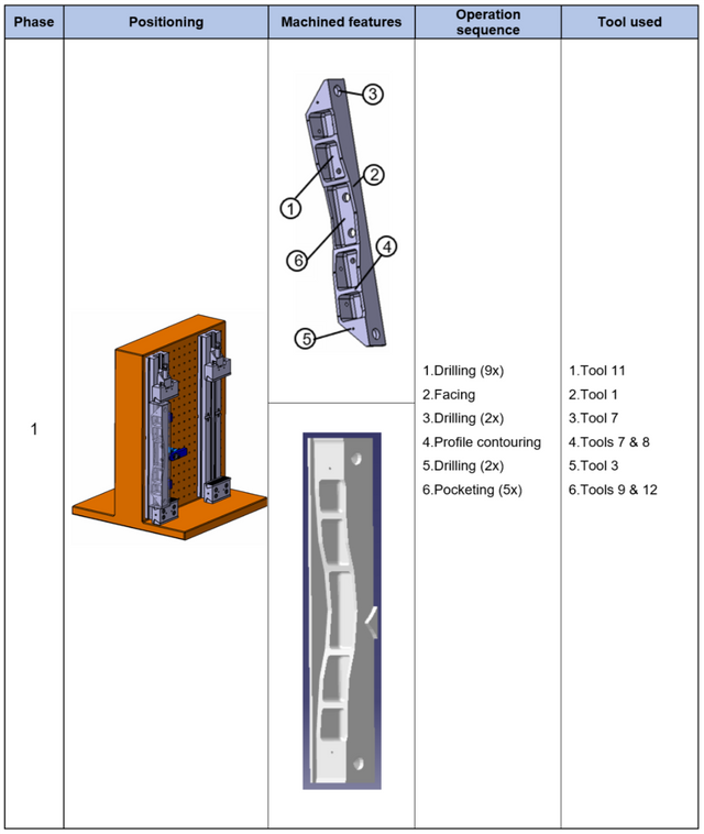
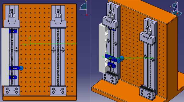
In the first fixturing we decided to perform the complex profile and the five pockets on the front of the workpiece. For this reason we used one of the modular vises supplied to us: this allowed us to properly fix the workpiece by temporarily sacrificing the machining of the heads, the rear and the top.
To prevent further movements and complete the 3-2-1 rule we have also added alternative clamping elements properly selected from the Gerardi catalogue:
- The standard clamps (S210 article) were used as a support for the work piece in order to avoid horizontal displacements.
- The shaped standard clamp (S211 article), in addition to keeping the workpiece in contact with the vise, avoids horizontal movements.
- The screw support (S120 article) allowed us to properly rest the shaped standard clamp.
- The studs, the flat washers and the turned tall nuts (articles S321, S370, S340 respectively) allowed the fixing of the previous articles on the tombstone.
Second Setup

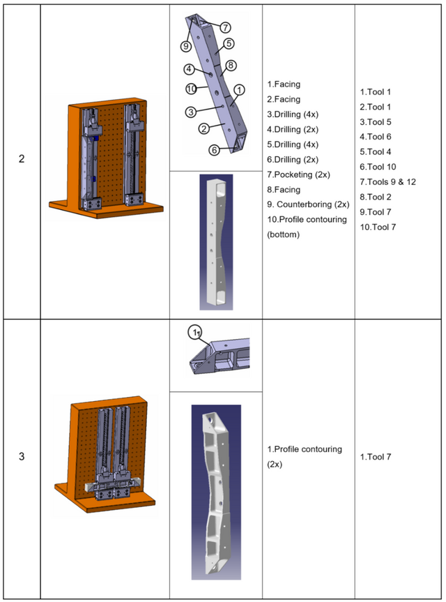
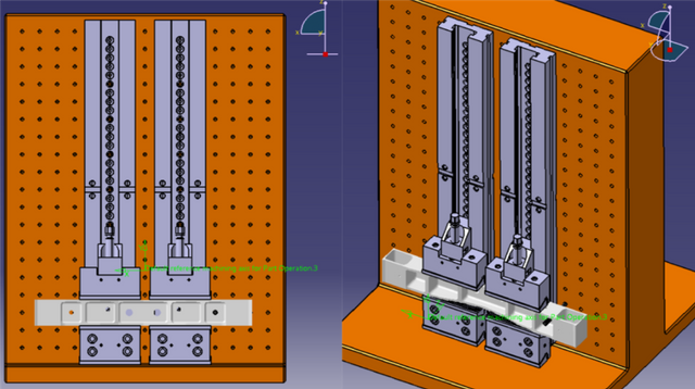
In the second fixturing we decided to perform the remaining facing operations to be able to get the two head pockets and the remaining holes done. To hole the workpiece we still have used one modular vise and we simply rotated the WIP in order to perform the head pockets.
Also in this step we decided to add some clamping elements from Gerardi’s catalogue in order to obtain a properly workholding device:
- As in the first step, the standard clamps (S210 article) were used as a support for the work piece in order to avoid horizontal displacements.
- The shaped standard clamp (S211 article) was used to properly fix the work piece to the modular vice making use of the previously machined pockets.
- As in the first step, the screw support (S120 article) allowed us to properly rest the shaped standard clamp.
- In the same way the studs, the flat washers and the turned tall nuts (articles S321, S370, S340 respectively) allowed the fixing of the previous articles on the tombstone.
Third Step

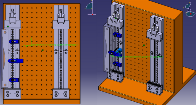
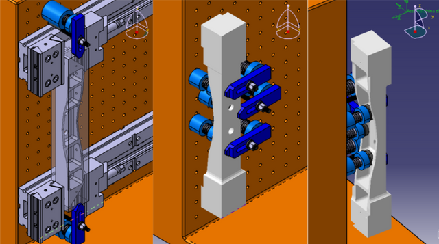
The third and last fixturing allows us to obtain the correct shape of our piece.
The use of both modular clamps provides an excellent grip avoiding vertical displacements. The only addition of the stud (article S321) enables us to fix the WIP.
This addition is possible because it has same size of the hole positioned on the bottom of the pocket and it perfectly fits into it.
Alternative Setup Definition

At the same time as the development of our main project, we decided to carry out another alternative project with only two fixturing setups.
This allowed us to test different tools and have a wider choice margin in order to obtain the shortest possible processing time.
This alternative was aimed at processing the main body in the first positioning and finishing the heads in the last.
For a better management of the work space, we decided not to use the modular vice in the second positioning, preferring different clamping elements whose provided us the right height and manoeuvrability.
The only additional Gerardi elements are the “V” groove caps (article S152) that allow the support and avoid vertical and horizontal displacements.
The shaped standard clamps (S211 article) complete the 3-2-1 rule completely fixing the workpiece.
Final setup choice
Despite a slight gain in processing time, we have chosen the three-placements setup. Above all we did this because we have considered the first fixturing much more stable in terms of minimized vibrations and thereby improved accuracy.
Conclusion
At this point, having defined the introduction, the choice of tools, the machining features and the setup definition, in the third and last part we will talk about machining operation and total time estimation.
Bibliography and sources
Tool Selection & Power checks
Mitsubishi - http://www.mitsubishicarbide.com/en/
Sandvik - https://www.sandvik.coromant.com/it-it/pages/default.aspx
Seco - https://www.secotools.com/Clamping elements selection
http://gerardi.it/prodotti/Textbooks
Manufacturing Engineering and Technology, SI Edition - Serope Kalpakjian, Stephen SchmidConcepts acquired during the university course
The images and tables were created by the Team Daedevils with the use of Word, Excel and the material provided by the professors.

ITA
Introduzione alla 2° parte
In questa seconda parte del progetto relativo al corso di CAM (Computer Aided Manufacturing), affronteremo gli argomenti che riguardano Identificazione delle caratteristiche di lavorazione e definizione dei Setup.
Se non avete avuto il piacere di leggere la prima parte, vi invito a dare un occhiata qui, dove troverete l’introduzione al progetto e la selezione degli utensili.
Buona Lettura
Identificazione delle caratteristiche di lavorazione
Per creare la parte finale, sono state utilizzate numerose funzioni: fresatura frontale, contornatura del profilo, trapanatura e tascatura.
Tasche
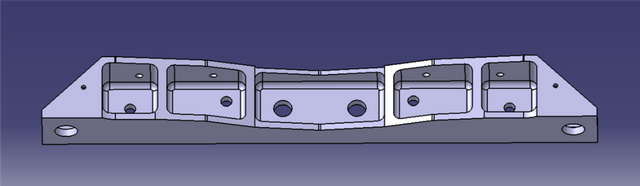
Il nostro pezzo contiene cinque tasche situate su un lato e altre due alle estremità della parte. Per creare ogni tasca abbiamo seguito una determinata procedura: prima di tutto con un trapano abbiamo eseguito alcuni fori che ci hanno permesso di rimuovere una enorme quantità di materiale.
Per le tasche esterne (60x60mm) è stato sufficiente un foro; due per quelle intermedie (85x60mm) e tre fori per quella centrale (140x60mm). Siamo così riusciti a massimizzare la quantità di chip rimosso.
Successivamente abbiamo eseguito una fresatura dei profili con una fresa per sgrossatura per i lati e di finitura per il fondo delle tasche: per questo abbiamo utilizzato un utensile con raggio di taglio di 6,35 mm che ci ha permesso di creare un percorso utensile più vicino ai lati.
L'ultimo passo è stato quindi la rifinitura dei bordi, che è stata eseguita con una fresa frontale con raggio di taglio di 6mm.
Filetto di bordo
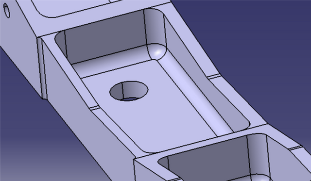
Il fondo delle tasche presenta un filetto di 6 mm che è stato lavorato nell'ultima fase di finitura con un fresa frontale da 6 mm.
Profilo di contornatura e spianatura
Per ottenere la forma desiderata del profilo anteriore e delle estremità, abbiamo eseguito diverse operazioni di contornatura del profilo.
Il profilo frontale è stato sgrossato con una fresa da 25mm, che è molto veloce a causa del piccolo ingaggio radiale, ma non può essere utilizzato per rifinire la superficie perché è troppo grande per ottenere la curva del raggio di 12mm al centro.
Per evitare questo problema scegliamo un altro strumento per rifinire la superficie e creare la differenza tra il bordo superiore e il bordo inferiore.
Per creare il profilo da 45 ° alle estremità è stata seguita la stessa procedura, senza la necessità di una fresa piccola.
Le tre facce che non necessitavano di un'operazione di profilatura sono quindi state sgrossate e finite attraverso una operazione di spianatura.
Il lavoro più pesante è stato eseguito con una fresa da 160 mm che ci ha permesso di ottenere un impegno assiale di 4 mm che conserva ancora buone prestazioni in termini di tempo.
La scanalatura nella parte superiore (con bordi da 2 mm) è stata lavorata con una fresa più piccola montando un inserto da 2 mm per ottenere la forma desiderata.
Entrambe le operazioni hanno richiesto un ulteriore passaggio per la finitura della superficie; abbiamo così deciso di utilizzare un impegno assiale di 1 mm.
Fori e svasature
La forma finale contiene 14 fori con diversi diametri: 5, 8, 12 e 25 mm.
Abbiamo scelto 3 punte con diametro da 5, 8, 12 mm per poter eseguire i primi tre tipi di fori. L'ultimo tipo è stato eseguito utilizzando una fresa D25 per il foro centrato, successivamente ingrandita utilizzando la contornatura del profilo per ottenere il foro svasato.
Riassumendo
Setup Definition
Primo fissaggio
Nel primo fissaggio abbiamo deciso di lavorare il profilo complesso e le cinque tasche sul lato anteriore del pezzo. Per questo motivo abbiamo utilizzato una delle morse modulari che ci sono state fornite: queste ci hanno permesso di fissare il pezzo, sacrificando temporaneamente la lavorazione delle teste, della parte posteriore e superiore.
Per evitare ulteriori movimenti e completare la regola del 3-2-1 abbiamo aggiunto anche elementi di fissaggio alternativi selezionati correttamente dal catalogo Gerardi:
- I morsetti standard (articolo S210) sono stati utilizzati come supporto per il pezzo da lavorare al fine di evitare spostamenti orizzontali.
- Il morsetto standard sagomato (articolo S211), oltre a mantenere il pezzo in contatto con la morsa, evita movimenti orizzontali.
- Il supporto a vite (articolo S120) ci ha permesso di appoggiare correttamente il morsetto standard sagomato.
- I prigionieri, le rondelle piatte e i dadi alti torniti (articoli S321, S370, S340 rispettivamente) consentono il fissaggio degli articoli precedenti sulla base.
Secondo fissaggio
Nel secondo fissaggio abbiamo deciso di lavorare le restanti facce per poter ottenere le due tasche frontali e i fori rimanenti. Per fissare il pezzo abbiamo usato ancora la morsa modulare ruotando semplicemente il WIP per eseguire le tasche alle estremità.
Anche in questa fase abbiamo deciso di aggiungere alcuni elementi di fissaggio dal catalogo Gerardi al fine di ottenere un dispositivo idoneo alla presa in carico:
- Come nella prima fase, i morsetti standard (articolo S210) sono stati utilizzati come supporto per il pezzo al fine di evitare spostamenti orizzontali.
- Il morsetto standard sagomato (articolo S211) è stato utilizzato per fissare correttamente il pezzo alla morsa modulare facendo uso delle tasche precedentemente lavorate.
- Come nella prima fase, il supporto a vite (articolo S120) ci ha permesso di appoggiare correttamente il morsetto standard sagomato.
- Allo stesso modo sono stati utilizzati i prigionieri, le ** rondelle piatte ** e i dadi alti torniti (articoli S321, S370, S340) per il fissaggio degli articoli precedenti sulla base.
Terzo fissaggio
Il terzo e ultimo fissaggio ci consente di ottenere la forma corretta del nostro pezzo.
L'uso di entrambi le morse modulari offre un'eccellente presa evitando spostamenti verticali.
L'unica aggiunta del prigioniero (articolo S321) ci consente di sostenere il WIP.
Questa aggiunta è possibile perché ha le stesse dimensioni del foro posizionato sul fondo della tasca e si adatta perfettamente al suo interno.
Fissaggio alternativo
Parallelamente allo sviluppo del nostro progetto principale, abbiamo deciso di realizzare un altro progetto alternativo con solo due posizionamenti.
Questo ci ha permesso di testare diversi strumenti e avere un margine di scelta più ampio al fine di ottenere un tempo di lavorazione più breve possibile.
Questa alternativa mirava a lavorare il corpo principale nel primo posizionamento e terminare le teste nell'ultimo.
Per una migliore gestione dello spazio di lavoro, abbiamo deciso di non utilizzare la morsa modulare nel secondo posizionamento, preferendo diversi elementi di fissaggio che ci hanno fornito la giusta altezza e manovrabilità .
Gli unici elementi Gerardi aggiuntivi sono i tappi per scanalatura a "V" (articolo S152) che consentono il supporto ed evitano spostamenti verticali e orizzontali.
I morsetti standard sagomati (articolo S211) completano la regola del 3-2-1 che fissa completamente il pezzo.
Scelta della configurazione finale
Nonostante un leggero aumento dei tempi di lavorazione, abbiamo scelto la configurazione a tre posizionamenti perchè risultava più stabile in termini di riduzione delle vibrazioni e maggiore precisione.
Conclusione
A questo punto, dopo aver definito l'introduzione, la scelta degli strumenti, le caratteristiche di lavorazione e la definizione della configurazione, nella terza e ultima parte parleremo di lavorazione e stima del tempo totale di lavorazione.
Bibliografia e fonti
Selezione utensili e controlli di potenza
Mitsubishi - http://www.mitsubishicarbide.com/en/
Sandvik - https://www.sandvik.coromant.com/it-it/pages/default.aspx
Seco - https://www.secotools.com/Selezione di elementi di fissaggio
http://gerardi.it/prodotti/Libri di testo
Manufacturing Engineering and Technology, SI Edition - Serope Kalpakjian, Stephen SchmidConcetti acquisiti durante il corso universitario
Le immagini e le tabelle sono state create dal Team Daedevils con l'utilizzo di Word, Excel e tramite il materiale fornitoci dai professori.
Daedevils
Seguite anche voi il tag #itastem e #steemstem per approfondire altre tematiche scientifiche!

Autore logo: @ilvacca

This is a test comment, notify @kryzsec on discord if there are any errors please.
Being A SteemStem Member
wow...sei un grande!
Wow..unbelievable technology..thats for real??
It's all true. You could search on youtube writing "CNC machining". You could get a better idea of this!
Finalmente un bel post tecnico di meccanica, modellazione, CAD/CAM.
E' da quando ho smesso di usare Inventor che non metto più mano su certe cose.
Ho visto che usi CatiaV5. Solo per studio o anche per lavoro?
ps. il 200esimo upvote è il mio :)
Per ora solamente per lo studio!! Ma chissà il futuro cosa riserverà :D
Grazie per il supporto ;)