S19-Wk3: Interpretation of circuit diagram/circuit building

Hi Student, welcome to our third week of electronics class. It is good that our training started the way it does two weeks ago and last week. The things we learnt on those classes would help us in today's class. Today's class would be an interesting one as it focuses on interpretation of circuit diagrams and building of a circuit. It's a shame few students participated in our last week tasks. We hope students will see the important of these classes and why it is purely practical.
But let's get a little tips before we proceed. One of the component we would use is a resistor and resistor value can be identified through their colour coding or using your multimeter.

Resistor colour code table
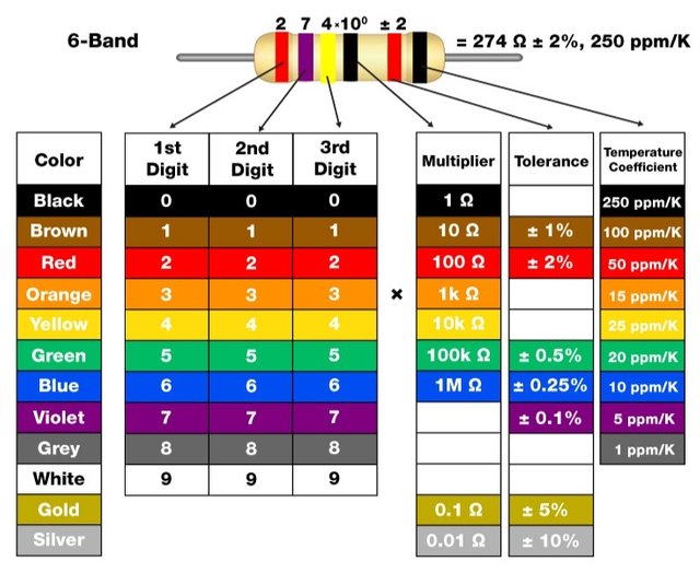
The first colour band indicates the first digit or number of the resistor value.
The second coloured band indicates the second digit or number of the resistor value.
The third coloured band indicates the number of zeros in the resistor value, that is the multiplier.
The fourth coloured band is the tolerance usually and most times it is gold or silver. THis colour indicate how accurate the resistor is with respect of its desired value.
Let's consider consider one example by identifying the resistor below:
- First band coulour here is brown which according to the table above is 1
- Second colour here is black which according to the table above is 0
- Third colour here is red which according to the table is 2
So the result would be : 10 X 100 = 1000

Don't be confuse, what we just did here is to combine the values obtained from the first band and second band and we then multiply it by the multiplier to get the resistance in ohms.
So we would make use of few other electronics components and tools. We already mentioned that students should get some of those tools and components as we would be using it in our classes. For now, let's see how we can build a simple circuit.
Interpretation of circuit diagram
Circuit diagram is a graphical representation of an electric circuit. Any electronic device we see today starts from a circuit diagram before it comes into reality. The diagram indicate the components used and how they are connected. That means, it is very useful to know all the symbols of components and their polarity.
You can read more about how to interpret a circuit diagram on the post entitled: Let's play with 555 timer IC
To get started in circuit interpretation, get these tips or steps handy in your finger tips...
First, identify the electronic components on the circuit diagram, note the symbols
(remember we have studied few symbols two weeks ago). Know where a wire is connected and where it is notStudy to check if the components are connected in parallel or series.
Identify the input and output
Check and maintain components values or equivalent
Build your circuit and check if it could give you exactly what it was design for
Workshop 1
In this workshop 1, we are going to put the steps we have above into practice. First we would build one simple circuit together and you would do the next one. Let's light up an LED with a 9V battery source.
Fig.1

Fig.2

So we have the full diagram above. And the components there includes :
- LED
- 1k resistor
- Jumper wire
- 9volt battery
Fig 1 shows and LED connected to a 9 volt battery directly through jumper wire while Fig 2 shows and LED connected to a 9V battery with 1k resistor attached.
Assignment
Task 1: Do the both connections with or without a breadboard, but it is more advisable to use a breadboard since we would be using it all through. Write your observation for the first experiment and diagram, do the same with the second.
Task 2: Draw a circuit diagram of an LED attached to 2 resistors of 1k ohms connected in series, powered with 9V battery source. What steps did you take in drawing this?
Task3: Explain the two circuits below, state their differences if at all there is any
Circuit 1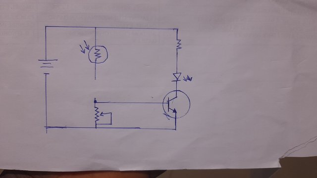
Circuit 2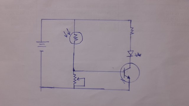
Task 4: Draw any complete simple circuit of your choice using some components we introduced in week 1, state it's function. (Professors could ask you questions based on any circuit you present, be ready to respond to it accordingly)
Task 5: Assuming 4 resistors are connected in series and they are: (Brown black black Gold), (Brown black brown silver), (Red black black gold), (Brown green red gold), what are those resistors?
Instructions :
- Please kindly read all the instructions we have on our post entitled: Reminders For Students in Electronics Academy. We would be working with those instructions STRICTLY

The participation schedule is between Monday, July 22 , 2024 at 00:00 UTC to Sunday, - July 28, 2024 at 23:59 UTC.
DO NOT wait till the last minutes to submit, you have the whole week to do your tasks.
Feel free to post in any language hence it can be translated on google translator
Please make sure to include our tag #electronicss19w3 among your first four tags for easy search.
DO NOT use any downloaded pictures on task 1, use your picture for that demonstration
Post the link of your assignment in the comment section of this lesson.
Avoid unnecessary long and irrelevant introductory
All our instructions are supper important and all participating students are advised to read and understand those rules/regulations.
Note to community curators:
Please NO community curator should use the SC account to vote any assignment in the "Electronic Academy" when such post is not verified yet by any of the professors.
Note to students:
Additional efforts will be taken into account , so try to be creative , original and show your interest in learning .
This lesson is more of practical because we are heading to somewhere. If you have completed all the tasks, please kindly wait for the professor's comments and continue studying to be prepared for the third week.
Goodluck
The Electronic Eagles Team
Great job by you, The Electronic Eagles Team , I appreciate how you provide a comprehensive guide to interpreting circuit diagrams and building circuits.i really like your detailed explanation and visuals. I also like how you broke down the complex concepts into steps, making it understandable.
This lesson is really heading to somewhere, though electronic is not my field butI learning mew things every day, adding to the little knowledge I had.
Estamos avanzando cada vez más en las lecciones, a medida que se avanza, más se aprende. En esta lección 3 los estudiantes empezarán a diseñar circuitos y poner en práctica lo que han venido aprendiendo.
Éxito para todos.
https://steemit.com/hive-188837/@manuelhooks/interpretation-of-circuit-diagram-circuit-building
https://steemit.com/hive-188837/@udyliciouz/s19-wk3-interpretation-of-circuit-diagram-circuit-building
My assignment
https://steemit.com/hive-188837/@lusciouslucy/s19-wk3-interpretation-of-circuit-diagram-circuit-building
Hola por aca dejo mi participación
https://steemit.com/hive-188837/@arnoldog25/s19-wk3-interpretation-of-circuit-diagram-circuit-building
Saludos