nd Home Automation Course||Lecture 3 Control AC Blub throug Relay | 20% rewards goes to siz-official
Greetings Steem Infinity Zone from @ammar79
.jpg)

I started Robotics, IoT, and home automation course here. Today is our 3rd lecture. in My previous lectures. I described the Basics of IoT and microcontrollers then connected and configured the ESP32 microcontroller with the Laptop. and then I describe basic hardware integration we controlled a led with a microcontroller after that we attached an OLED display
Today I will describe the function relay module and how it works. we are using an electromagnetic relay. I will describe everything with examples
For Beter Understanding I also Make a video Tutorial for this lecture.
here are the links of my Previous lectures
Lecture 01
Lecture 02
in today's lecture, we will continue our previous lecture and some interesting programs.
Lecture Outline
1. introduction to relay module
2. Controll AC Light with Relay
3. ON and Off AC light From Serial Monitor
1. Introduction to Rlay Module
The relay module is basically used for switching. when we need to control High voltage things through our microcontroller then we use a relay module. we are using an electromagnetic relay in our project. Here is the structure of the relay
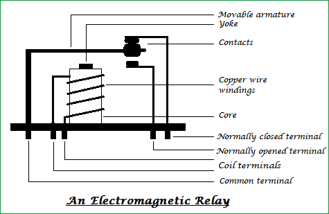
Image Source
as shown on diagram relay module have three high voltage terminals
1. Common terminal
This is the main terminal where we apply the main voltage from the live current
2. Normally open terminal
In the rest state of the relay, this terminal connects with a common terminal. When there is no signal to relay module this terminal have the same current which we provided on the common terminal
3. normally close terminal
when we provide a flag signal to relay the common terminal connects with this terminal and disconnect from the normally open terminal
Electromagnetic relay works on the principal coil magnetic field. this relay module contains a coil that produces a magnetic field that attracts or repels the switch, as a result, the switch changes its position from a normally open terminal to a normally closed terminal. for this, we have to provide a flag signal to the coil according to the flag signal internal circuit board provides charge to the coil.
Relay Modules are available in many Channels it can be single and multi-channel. I am using a 4 channel relay so I can control 4 things through this relay buy the relay module as per your requirements. The number of pins on the relay module depends on the number of channels.
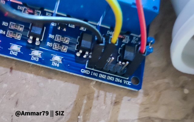
Two pins are always fixed for voltage in every relay module. and the other pins indicate the channel number for example a four-channel relay has 6 pins, 2 for the power of the relay and 4 for the channel. when we have to switch on a relay we just write high voltage to that relay pin
2. Controll AC Light with Relay
Now we are going to control a full voltage home light from our microcontroller with the help of a relay
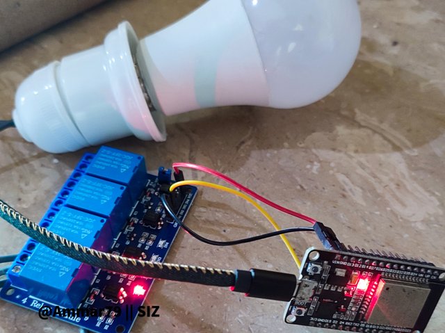
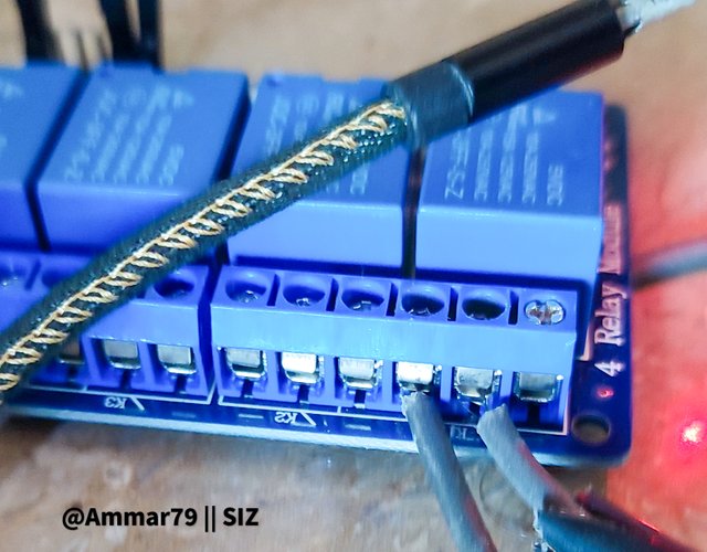
I am using the 1st channel of the relay for this first I have connected the main electrical wire with the common terminal of the relay then o connect the wire from light to normally closed terminal.
then I connect the power pins of the relay module to the microcontroller and finally connect the relay channel 1 pin to digital pin 2 of the micro controller.
Here is the code to blink the High voltage light
void setup() {
pinMode (2, OUTPUT);
}
void loop() {
digitalWrite(2, HIGH);
delay(100);
digitalWrite(2, LOW);
delay(100);
}
We are already familiar with this code. we used it in our first lecture for blinking an led light here again we are using the same code for switching the relay module. we are just writing relay connected on and off after the 10-mile seconds
3. ON and Off AC light From Serial Monitor
Now we have successfully connected and controlled our relay with a microcontroller. Now we control the light with the help of the serial monitor. In my previous lectures briefly described the working of the serial monitor
here is the code to control light with the help of the serial monitor from computer
char data = 0;
void setup()
{
Serial.begin(115200);
pinMode(2, OUTPUT);
}
void loop()
{
if(Serial.available()>0 )
{
data = Serial.read();
Serial.print(data);
Serial.print("\n");
if (data == '1')
{
digitalWrite(2, HIGH);
}
else if(data == '0')
{
digitalWrite(2, LOW);
}
}
}
Almost the same code we have already written in our previous lecture. Here we are just taking 1 or 0 as input from the serial Monitor and storing it into and variable then we are comparing the variable with if-else statement and writing relay pin according to the input.
That's all for our 3rd lecture. You can ask any question in the comment section
In the next lecture we will control the same light from wifi or the internet.
Good one post bro keep it up and keep learn with our steem fellows and friends and newcomers.
Regards, Faran Nabeel
Thank you