Solar power project step 3, circuit designs for charging / power out switch for continuous(ish) use, and new batteries
Part 2: Solar power project step 2, battery test with inverter
Part 1: initial purchase and testing
After my initial testing with my solar charged batteries, things are looking good. While the capacity is relatively low for normal every day uses, this is just the way it is with batteries. It really shows me how I have taken for granted the power supply from "the wall", from the power stations, and just how much energy I must be using every day, even only in electricity.
I had two 12v 7 Ah batteries, and I have now added two more I was able to pick up cheap just before my local Maplin shop closed for good. I got two 12v 4.5 Ah batteries, that's the biggest capacity they had left at 12v. I was kicking myself I didn't get more 7 Ah, but then again these are disposable income purchases, and I only have so much of that per period of time. I'm lucky I have the cash to buy them at all really!
The 4.5 Ah (pictured below, after first circuit diagrams) are a lot more blocky. Now I have a total of 23 Ah power I can deliver with full batteries at 12v, or there abouts.
Combining them all into a power pack
I only have one solar regulator and one solar cell (of any significant size / power anyway) and now that I have 4 batteries I can't charge them all at once. In any case it seems most useful to create a little battery pack system to charge at the same time as using the batteries, especially since it looks like charging them fully from (Irish!) sun takes a long time.
I have a few easy to use relays in my box of random electronics and went about planning a circuit to use them to switch between the batteries getting power, or charging. First draft is just the circuit without considering how it might look physically.
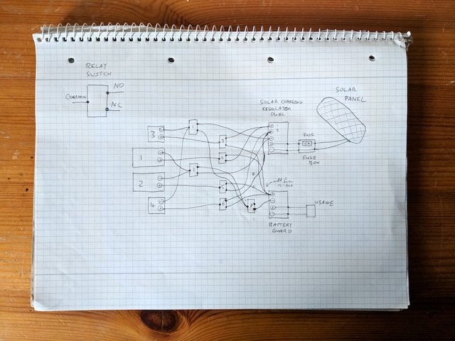
I know what you're thinking: I should have used colour! I didn't have any good quality colouring pens or anything around so I opted for solid black, at least it's clean.
In case you're not familiar with "relays", they are switches which switch a switch on a completely isolated other circuit. That is, the circuit controlling the switch is not the same circuit (usually) that gets switched. It's useful for say a very high voltage circuit, like a mains switch, being controlled by a very low power microcontroller unit. You can think of it like your finger not getting you electrocuted when you switch the lights on in your house, there's a separation. In my case that's kind of what I have, I'll be using a Particle Photon microcontroller which operates at 3.3v to switch the batteries at 12v, and I don't want to get in the way of the batteries circuit with the microcontroller.
Relays have three terminals on the switched side, normally closed (NC), normally open (NO) and common (COM). The common is always connected, and the switch switches between connecting it to NC or NO depending on if it's active. In it's off state, i.e. unswitched, i.e. no power to the switch indicating it's "on", NC is connected. That's because it's the terminal that's normally closed. "Closed" here doesn't mean blocked, as we tend to use it in daily speech, but that the circuit is closed, i.e. connected. The gap is closed, that's the word usage.
So now you can read the diagram, if you couldn't before. On a relay, the bottom right terminal is usually connected.
I chose to group the battery terminals symmetrically (I have a vague sense you're supposed to do this for some reason), so the two 7 Ah are charging or the two 4Ah are charging, grouped by negative terminals via relays number 1 and 2. However I gave each battery its own independent positive terminal switch, numbered 3 to 6. This is because I tried both 7 Ah batteries in parallel (voltage the same but current added) and it blew the 15 A fuse I had!
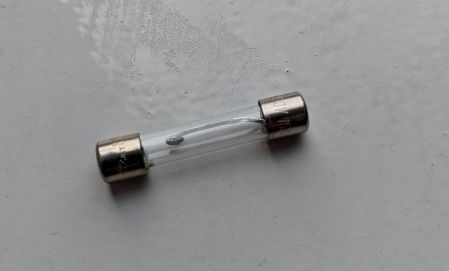
Here you can see the quick blow 15 A fuse melted, that metal inside the glass is supposed to go from one side to the other. I'm glad I checked ahead of time because it was important to find that out. I don't really know why 7 + 7 Ah = 14 Ah was able to blow a 15 A fuse, some kind of surge I suppose, but it did and I'd prefer to play it safe.
In the circuit there's also a master switch, numbered 7. This means that positive terminals can be directed to the battery output but not actually active. There's actually a mistake in the diagram, relay 7 should have nothing connected to NC terminal and connected on NO, so that unless actively chosen it is safely off. I corrected this later.
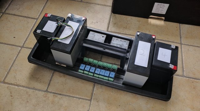
Mock container and layout of parts
I was struck in a moment of inspiration that things might fit well in the top of a tool box compartment I had. My intuition was right and everything fit extremely well, including the 7 relays I would need. Here's the mock set up just loosely sitting in the box.
Additionally here you can see another unit I got when I was buying the 4.5 Ah batteries, a "Battery Guard". This is to shut off access to the batteries when the get too low to protect them from completely discharging, which apparently is bad for them I've discovered. It also has a light indicator which is useful to see that there is charge coming out and the circuit is working.
I actually can't believe how well they fit, it really is amazing to me. It even has a handle for lifting and the plastic is very sturdy. These four batteries are pretty heavy all together, so that's good. I was encouraged by this and went on to try to find the most efficient way to wire it up, and think of what else I'd need.
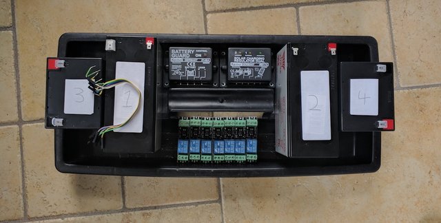
Wiring up diagram with actual locations
It took me a few days in the time I could steal away to do this to figure this out. I think I went through 5 or 6 drafts. Here is the result.
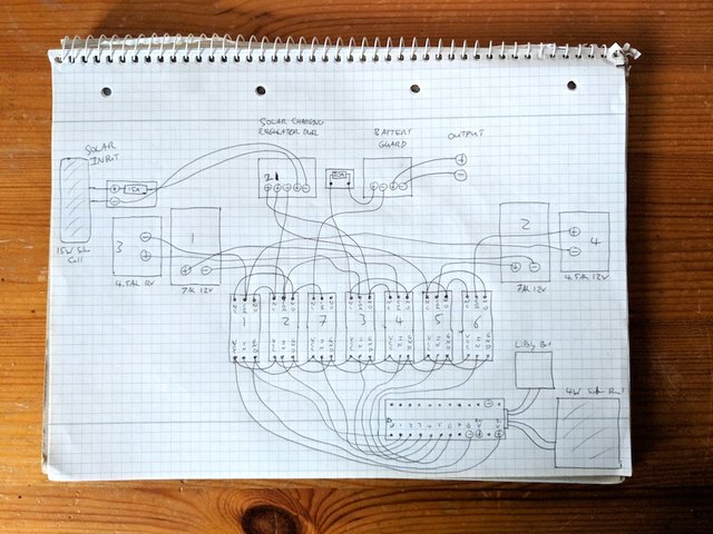
Again, no colours! And that makes this one really hard to read, sorry about that, and also sorry to my poor brain and eyes, it was a bit harder to do because of that. I should have just got some crayons or something! I think I'll mark this up in the future, but for now this is the best I have.
The main things you can see are:
- the batteries in the wings, balanced symmetrically (mainly to make carrying easier and safer),
- the row of relays at the bottom,
- the two regulators at the top (input on left, output on right, unlike the photo test above), with fuses,
- the main solar cell at top left, and
- the control unit with battery and small solar cell.
The control unit at the bottom, the "brain", comprises the Particle Photon, which LiPoly battery to keep it running, and it's own 4 W solar cell to make it fully off grid and sustainable (hopefully). I've even done the pin outs for the microcontroller to the relays.
The relays need power to operate, as well as power to the switch terminal, and when you add the mandatory ground terminal, this is three terminals for the control side. The controlled side is as described earlier, NC / NO / COM, with COM in the middle physically.
It's the same as the diagram at the top, even with the mistake of relay 7 on NC instead of NO!
How am I going to put this together
The thing I'm scratching my head about now is how to do all the wiring neatly. The middle wiring looks like it will be tough because it's so tight and there's so many short wires, but doable. It will be tougher too because I don't want to use too thin wires as this doesn't allow for high enough current delivery (I read that in one of the instruction sheets with the regulators).
The fuses are one of the big unknowns, not sure how to do that tidy. Also where do I put the microcontroller? Looks like it will have to be on top of the relays practically but I don't know in or on what.
At least the main work is done in terms of planning. It was hard to wait and not just dive in, but that patience comes with being an adult, I wouldn't have done this so carefully in my younger days!
Next I'll attempt to put this monster together, very excited to do that.
I hope you enjoyed this part of the journey. If you did please consider supporting my blog with an up vote and a resteem, I'm just starting out and would greatly appreciate it.
You have a minor grammatical mistake in the following sentence:
It should be its own instead of it's own.That's so funny, what an interesting and useful bot. I fixed it now, thank you.
Great post @fourth.. Loads of useful information here.. and nice to see how you CAn do it with very small batteries and DIY approach..
and.. guess what!?
Congratulations @fourth your post had been selected for an upvote worth ~$1.67 as part of the @ecoTrain minnow support project. Your upvote will come soon!
I hope this encourages you to keep writing amazing posts and making this world a better place!.
JOIN US ON DISCORD
https://discord.gg/XwAmRWW
Thank you @eco-alex, happy for the support and comments.
If you would like the help, I would be happy to coach you. You have a good start here, and since you are using a microprocessor there are some things you can do to enhance your system.
On Amp/Hour ratings, a 7AH battery will provide 7 amps for one hour, or 1 amp for seven hours. Unfortunately for your fuse, it will also provide 14 amps for half an hour, depending on the load.
Very detailed post, good work too!
Hi @smithlabs, listen thanks a lot for your comment, I took a break from social media for a while so I am only seeing this now. Thanks! I developed the system a bit further so I'm planning on posting about that in the next few days.
You know what you made me realise with this post, that the draw doesn't stop at whatever the rating is at 1 hour! I just made a mental error that it would at most give 7 amps, not that that would ramp up massively to meet the draw. So thanks.
Glad I could help! There are current limiter circuits, but they are more difficult. Batteries are not in any way smart, it is more like a team of horses. They will run until they drop, unless you control them! You are the driver, and you have to pull back on the reins, by controlling the load. Then you also have to run the brake, to keep them from running away; by installing a fuse or a breaker.
Have a lot of fun, and I hope you get a lot of free power!
:)