Building a X-Air Ultralight Aircraft
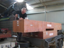
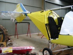
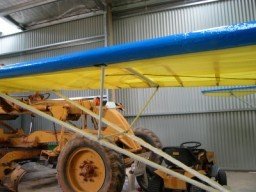
It's a very exciting day with my X-air kit had arrived in our shed.
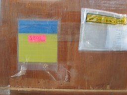
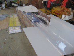
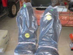
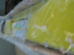
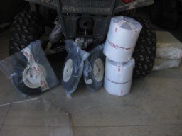
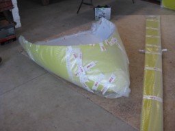
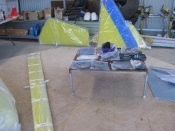
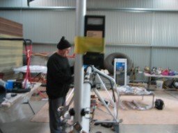
My Dad and I along with my good mate Pete took apart the two large boxes to see what’s inside and I was impressed at the packaging of how well it was all packed and happy to see no damage to any of the parts.
We sorted the parts in sections to see what was what placed each section out on our floor.
Build Day 1 & 2 of build
Both dad and I watched the build DVD produced by Michael Coates of X-Air Australia a few times which gave us a good understanding of how it was built.
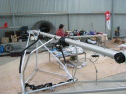
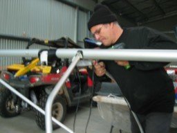
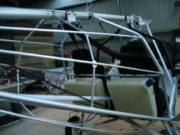
The first job was to assemble the main fuselage boom, all the bolts and fittings we loosely installed so that selecting the right bolts would not cause issues and made the build so much faster by not having to find and measure each bolt and bracket. This was a simple step of sliding the rear section into the front section and placed a pop rived at the pre marked location them we put the bolts back in place.
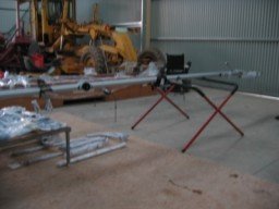
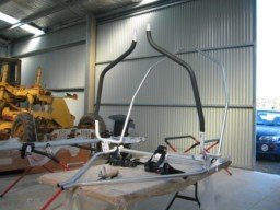
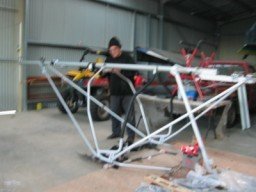
Next was to assemble the fuselage cabin frame parts onto the boom along with the factory made bottom fuselage frame and front nose gear support post as per the manual, at this stage we only had tightened the bolts to make sure nothing was forced in position.
Build Day 3
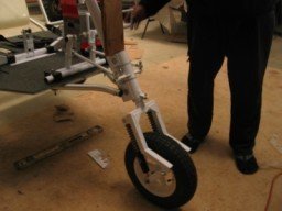
Today we assembled the nose gear, front wheel and the rear landing gear, on fitting the rear wheels we had to grind off 1mm on the wheel shim tube to that the wheels spin free once the outer bolt was tightened.
We attempted to fit the rudder post into the rear hole in the boom but we had an issue of the boom factory drilled to small so we left it to sort later.
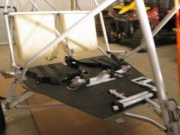
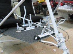
We then started to assemble the floor controls by bolting on the joystick plate, and aileron pulley systems that sits under the floor and fitted the cables in place to complete this assembly, foot peddle etc.
Build Day 4
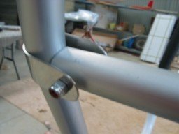
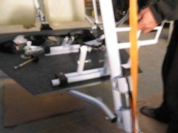
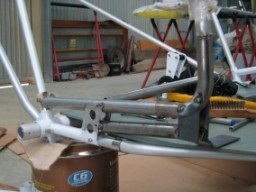
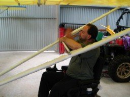
Today Dad made a reaming tool from a model heli tail boom to re size the rudder hole to get a perfect fit into the boom, once this was fitted we used 3 incidence meters to square the rudder post to the base of the main frame. One was placed on the main boom to get it sitting level (zero degrees) 2nd was placed in the main landing gear post to level this to zero and the 3rd was taped to the rudder post to make sure the rudder was aligned to the main fuselage, we ties rope to the top and bottom ends of the rugger post to get it straight, it first is was 1 ½ deg out to the frame so we adjusted the ropes to get it to sit at 0 incidence and then drilled out the align plate and done up all the fuselage bolts to lock the frame together and re checked it which was spot on straight.
Build Day 5
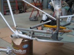
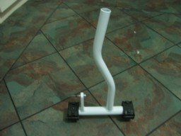
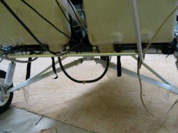
Today we mounted the fuel tank support pipe which I ground the ends of the pipe until there was a gap between the pipe and plate as if I left it the pipe would rub away at the main pipe and cause a failure, I didn’t like it being such a tight fit to rub and the stainless brackets hold it all in place so having the gap worked so much better.
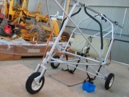
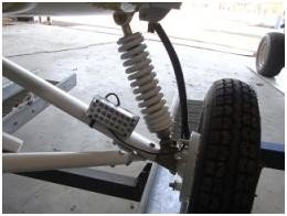
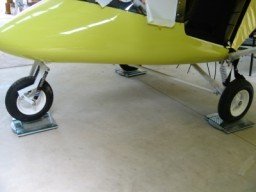
Next I bolted the fuel tanks to the frame with the brackets supplied and checked to make sure it was all properly installed. We also added the gear shocks and finished the main landing gear so it can sit on its wheels
We also installed the long elevator pipe which bolts to the pivot between the fuel tanks and the rear pivot plate that mounts at the front of the rudder plates.
Build Day 6
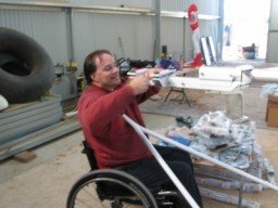
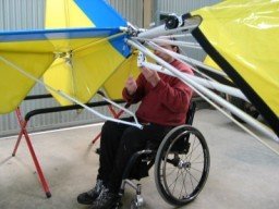
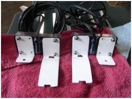
Today we installed the floor assembly and done the first of the mods for my wheelchair access, the two right side foot plates were cut off so that my feet wouldn’t tangle my feet in flight. See pics below
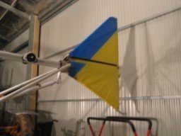
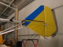
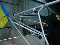
Next we fitted the rear fin fabric in place and installed the top and bottom front fin pipes, this too allot of mussel to fit in place. All the bolts were tightened up and re checked alignment which was Zero...
After that Dad and I bolted the rudder in place and added a shim to the middle hinge so that the hinge's were perfectly inline with each other, this little modification made the rudder turn left and right with no binding of the movement, I then installed the safety rings to the bolts on the hinges to complete the build of the rudder.
Build Day 7
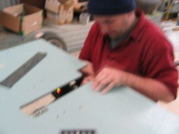
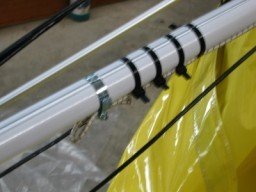
Today’s job was to connect the rudder and aileron cables through the pulley system at the seats as well as follow them up to the rear end of the boom where the rear 4 pulleys are located. Between the two lots of cables there are factory installed nylon tubing on each cable to stop them rubbing together, to secure them in place I heated the end 2 in with a heat gun then while warn added a zip tie to keep them in place.
We also drilled the nose gear locking bolt in place and made sure it was aligned square to the rudder pedals, we installed two springs to keep the rudder in the center when the stick is let go to give hands of flight. We took them off until we fit the body later.
Build Day 8
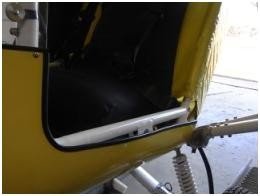
Today we modified the entry to be wider so that I can get into it easier. The frame was moved forward and dad added an extra support brace to the floor pipe to lock the frame in place, the mods are stronger than the standard kit frame so it has been well worth the effort to do.
Build Day 9-10
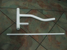
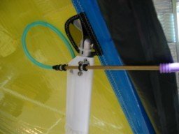
We fitted the seat which was just a case of bolting them to the floor with 4x bolts and there are two zip ties at the top to hold them against the fuel take mount pipe. Next we made a center rudder stick and throttle for my flying use and had it welded and powder coated in white, we used the same nylon blocks that was used for the standard throttle. We installed the middle elevator pipe and the elevator trim lever as per the manual. We also fitted a high quality fuel tube between the main tanks and replaced the standard clamps for a better one. Foam was also placed and glued between the fuel tanks and seats so that they don’t rub together which can happen after allot of flying.
Build Day 11-12
Once the foam was installed we tightened the lower fuel tank straps in place and secured the floor to the main pipe with 6 h/d large zip ties then checked over the section to make sure everything was finished properly. Happy with the build we cut all the zip ties back.
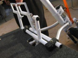
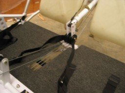
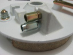
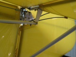
The below pictures show the details of the center rudder stick we made as well as the shims. The bend in the rudder control pipe is to clear the middle elevator lever.
We installed the left side toe brake cable into each footplate and ran them to both the rear wheels. The front ball end rods were fitted to the nose plate and foot plates and aligned total setup. I purchased two extra cable systems and ends and drilled and tapped an extra adjuster hole in the rear brake hubs so that I can install a throttle w/ handbrake on my joystick. Once I fitted the ends into the hub we reinstalled the hub and wheels.
Build Day 13-14
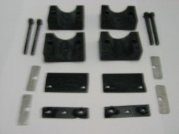
Today Dad and I mounted the new made rudder control joystick to the floor using the over sized blocks we got by mistake in the kit so these came in handy after all. We fitted the control rod and adjusted it square to the peddles and locked the ball ends in place with the locknut. I added a bike brake lever to my side joystick so that I can brake both rear wheels at the same time and this lever also has a handbrake function too which will be great for engine warm ups. I added a push to talk button on each joystick.
I fitted the dash to the top dash panel and made blind nuts glued to the front dash to make bolting it together easy later. I also started to fit the switches to the front dash panel.
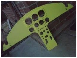
I drilled out and trial fitted the gauges to the dash and once happy I removed them all and painted the front dash yellow with 2pac paint.
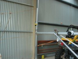
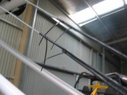
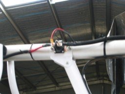
I made a custom VHF antenna to match my microair 760 radio from a nylon block which has two groves at a angle of 120deg which I placed piano wire cut to 23” which I mounted a BNC plug to connect my RG58 coax wire too. Each of the two wires I soldered to the two ends of the BNC plug which gives me a fully directional radio signal. I then purchased a swage tool and made a custom lead that connects to the radio set.
Having tested this I get a clear radio signal even inside our shed. I tuned it to Bendigo 119.3 to listen and had incoming signal chatting very clear which was a great build that was cheap.
Build Day 15-16
Today Dad and I installed the single brake lever on the right side joystick using a double cable lever from a quad bike which had a pre fitted handbrake lock as I could lock the brakes without having to hold the lever all the time.
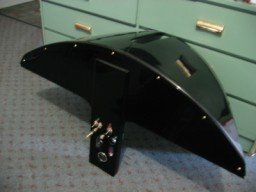
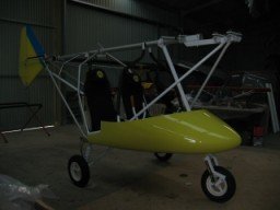
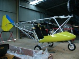
We fitted the front body to the frames which needed some dremel work to get a nice fit where the nose gear exits the body. We also fitted the rear lower fuselage stringers and fitted the two bolts that mount the stringers to the rear of the body.
Next we bolted the rear fuselage stringers in place as per the manual which had all the parts numbered and was a case of bolting it together and riveting the plates to the fuselage frames.
Build Day 17-18
I installed the switches on the main dash panel and added blind nuts to not have to reach under the dash to mount it to the upper dash. Next we installed the windscreen in place having watched the X-Air build video one more time to get tips on installing it which was done with the dash panel held in position and dad was inside the body as I drilled the holes from the outside adding a 4mm bolt in each hole starting from the center working out to each side, this took allot of patience to get it nice and straight but the end result was great.
I then took the dash of so I can install all the gauges etc to the panel and re install it later.
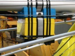
We added the breather pipes to the top of the main fuel tanks and zip tied the tubes to the tank outlet pipes, next we made s stainless steel bracket to hold the battery onto the main boom and placed it at the rear end in an approx place until the CG was worked out later.
Built Day 19
Today we installed the main fuel lines, fuel filter, electric fuel pump and the primer bulb. I added a T piece just before the fuel pump to connect to the primer bulb so that it is not on the pressure side of the electric pump. We also connected the two main tank drain holes with a 1/8 fitting and connected the two tanks together to a quick valve mounted on the left side wing strut plate so I could reach and check the fuel system easy.
Build Day 20
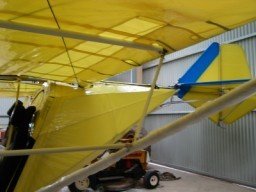
Our next exciting job we are up to is the installation of the main elevators and tail plane.
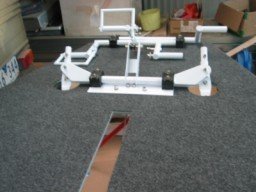
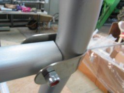
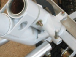
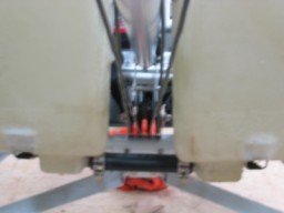
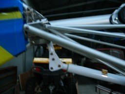
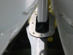
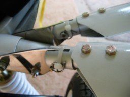
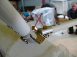
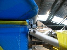
We bolted the two tail plane parts to each side of the rear tail boom using the pre installed bolts but we also decided to shim the front pipes so that they sit in the brackets without bending the mounts as per the pictures below.
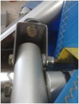
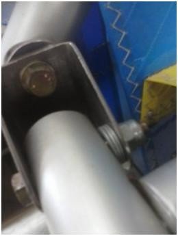
After fitting the tail plane in place we fitted the two tail plane struts and bolted the elevators to the tail which were factory assembled but when we connected the hinges up (3 on each side) we noticed as we moved the elevators up and down the tail plane was twisting which we found the three hinges were not in line with each other, to test this we loosened the middle bolts on each side until there was no twisting which we then added a 3mm alum spacer to each middle hinge and now they move smooth without any binding and the tail plane has no twist. I next bolted the Y elevator rod to the two elevator horns with the pre installed fittings.
Build Day 21
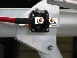
I had a + red battery lead custom made which was installed to the starter relay and fed down the boom to the battery and the relay was mounted to the post support plate just above the windscreen so that its earthed to the fuselage frame. We made a smaller lead to connect to the black – side of the battery and fitted this too the rear frame boom section.
and then installed the elevator pushrod bungee cord to the pipe which adds up pressure to give the control a easier feel we then fitted the luggage bag behind the seats and once happy we both checked over the total rear section to make sure everything was finished then put rear fuselage body cover so it can relax over the frame before its properly fitted with the zip ties.
Build Day 22
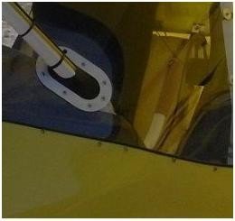
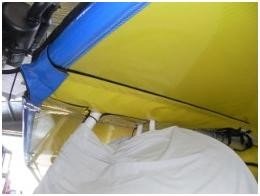
During the week I made some aluminium plates and a rubber boot from a car tube to cover the gaps on the windscreen where the center post and engine support posts exit the lexan window. These were fitted to give a much better look as well as sealing the air gap on the screen. We also finally finished the windscreen trimming at the entry area too.
During the week I took all the parts home to fit the instruments to the main dash panel which included ASI, ALT, VSI, RPM, Water Temp, EGT, Radio, volt gauge, hobbs etc.
The mail wire loom was included in the kit which was neatly connected to the panel ready to re install back into the plane, in the excitement I forgot to take pictures of the completed dash before installing it in the plane.
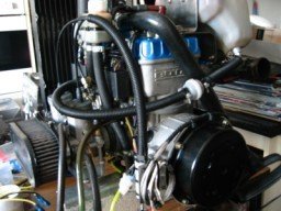
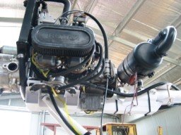
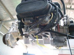
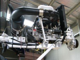
I had put aside a purchase I made in November 2011 of a used 212.50 hour oil injected Rotax blue head 582 dual radiator engine which was fitted with a 3:1 electric start gearbox and just what I was going to install.
For my piece of mind I replaced the top carb rubbers where the throttle cables exit, new rubber carb joiners between the engine and carb, new spark plugs, new exhaust springs, re wired it to match my X-Air loom. The gearbox oil was replaced and tested the compression which both cylinders had 132psi which is above the Rotax range 100-120psi.
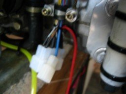
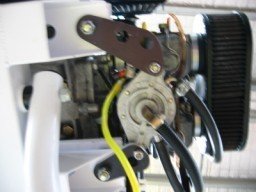
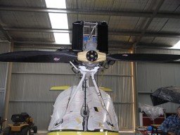
Build Day 23-24
Today we fitted the engine to the fuselage using a block n tackle mounted to the shed roof. The engine has vibration mounts fitted included in the kit we aligned with the aircraft mount and once lowered in place the bolts were added to fit it in place, we installed the exhaust having made a custom mount bracket for it, added a extra earth lead bolted where the pullstart is and back to the body for a proper earth connection then fitted the voltage regulator, fuel regulator, wiring loom which goes down the center pipe and connects to the dash panel and zip tied all the wiring in place.
Build Day 25-26
Fuselage put to the side for now and on to the wings we go
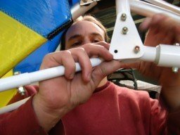
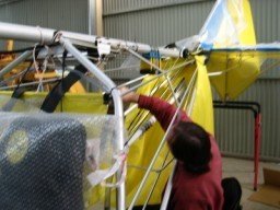
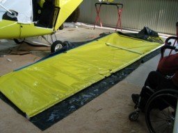
We first joined the leading edge and trailing edge of the right wing side. All the needed bolts were already in place so it was a case of sliding the two parts together and located the alignment hole which I added a pop rivet to secure it in place then re fitted the cable and strut mount plates.
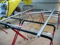
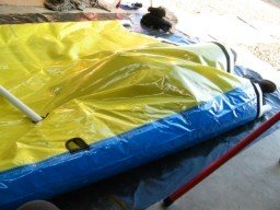
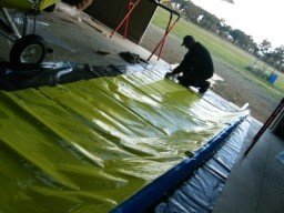
Next we placed the wing fabric on a mat to protect the surface and inserted the leading edge pipes inside the wing and fitted the wing tip pipe to hold the leading and trailing edges in the position. Dad got inside the wing and connected the cables to the wing pipes which locked the wings in place then we connected the two support pipes joining the LE/TE together.
Build Day 27
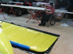
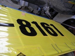
Today we assembled the left wing in the same way we built the right side. Before putting it on the fuselage we put the wing on a bench and added my rego numbers 19-8161 as it would be too hard to put them on after the wing was fitted. We marked a straight line where we wanted the numbers to sit and used soap suds to move each number in position.
We rubbed the decal with a plastic card to squeeze out the water and applied heat to the decal to glue it in place which took most of the day but got a great result.
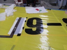
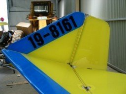
While we had a good thing going we also added the smaller numbers to the rear fin of the as per the RAA requirements, this was quicker as the printed decal was on one full backing sheet so the numbers kept the alignment perfectly.
One was installed on the left side and another fitted to the right side of the fin as to be seen from both left sides, only one wing is needed to display the rego numbers.
Build Day 28
Now the wings are built and ready to install on the fuselage Dad and I stacked two folding tables and some cardboard which we balanced each wing on and slowly moved them to hook up to the mount plates on the fuse, we found it best to bolt the trailing edge first then move the leading edge forward until the front plate lined up to install the pin.
With the wing bolted in place we fitted the front and rear wing struts to the mount plates at the fuselage then connected them to the wing front then rear pipes, once this was done we moved the tables away and completed the other wing install. I fitted the jury struts between the wing strut and main wing pipe then locked all the safety rings in place at each point. Once I was happy I then secured the safety rings to the pipes with a zip tie on each so that they are not rattling in flight.
Build Day 29
Today we connected the rudder cables to the fin and mounted the cable guide tubes which hold it in place just under the elevator one on each side. We also installed and set up the elevator trim system and zip ties all the cables and connections in place.
Next we got back to the wings and installed the ailerons with the factory and bolted the assembly onto the wings, next we connected the lower aileron cable system which had one turnbuckle to set the tension later. We connected the two cables that control the aileron from the joystick which are fed to the rear boom pulley and forward to connect to the top part of the aileron horn. Once the aileron cables were connected we placed two pipes wedged between the wings and strut and taped them in place so that we can set up the aileron deflection.
We lifted the aileron on the pipe about 8mm and once we centered the joysticks we adjusted the turnbuckles so it was all set in the center, we adjusted the turnbuckles so there was no play on the joystick and tie wired the turnbuckles so the cant undo in flight. While the sq pipes we taped to the wing we also checked the wings to each other to make sure they had the same incidence and washout then secured it all in place.
Build Day 30
I made a Pitot tube and bracket to be bolted to the right wing leading edge and ran a breather tube down the inside of the front wing strut, next I connected the air tube to the dash panel which links up to the ASI, ALT and VSI.
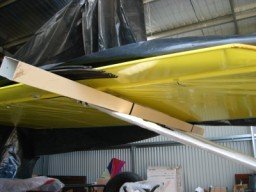
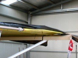
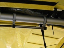
We installed all the inner wing ribs on both the left and right wings which were then straps fitted to the center section to pull the wing covers together and tension up the wing fabrics. To make it easy for me to get into the plane we constructed a grab handle mounted to the main boom using pre made pipe clamps and a piece of steel pipe as per the below pictures.
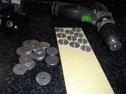
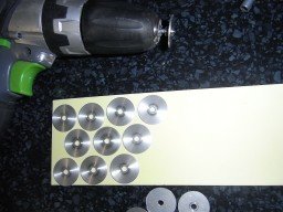
I made alum washers which were double sided taped to the holes we drilled on the screen to stop and cracking of the windscreen, I also made an extra windscreen support that clamps to the center nose gear pipe which will stop the screen from buckling under the wind pressure of flight.
Build Day 31 & 32
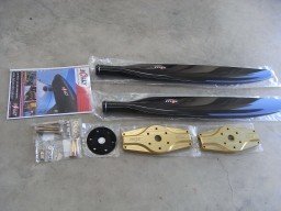
Today we assembled the Bolly carbon 68” prop that was matched to my 3:1 gearbox. We first tested 16.8deg but it was to high on revs so we changed to 25deg and dropped to 5900 so went for a 3rd go and settled on 22.9 deg pitch which gave us a full throttle around the 6500rpm which was ideal for the factory specs.
Next we installed the Lights to the landing gear with some custom brackets I made which are bolted to one of the strut bolts and the other side has a zip ties holding it to the pipe. The wire was channeled next to the brake cables and we added some cable wrap around the light wire and two brake cables on each side to give a neat look and stops the wire catching sticks etc. The light system gives me either a solid landing light or a flying strobe wigwag light which I connected to a three position switch which is connected to the main 12v power accessories loom.
Build Day 33
Today having finished all of the plane I wanted to tidy up some of the areas I was not happy to look at so I first installed some rubber channel to the body where the entry is, we finally installed the last wing under cover which was held with Velcro, next we gave the plane a full going over to make sure all bolts were tightened, zip ties all finished, wheels and brakes clear of movement, wheel brakes working good, engine runs good, nose tracks straight.
Last was to re check the CG as per the X-Air manual, I purchased three scales to do this job which we checked earlier but had to move the battery back to get it right. We filled the main tanks with the reserve fuel of 10 litres as per RAA requirements.
Weights are (A) Nose: 34 / (B) Left main: 114.5 / (C) Right main: 111.6
Total weight is : 260.1 KG
CG is to be between 9 and 19 range. CG=146xA / A+B+C
CG= 146 x 34 = 4964 divided by A + B + C 34 + 114.5 + 111.6 = 260.1
CG= 4964 / 260.1 = CG = 19
Total Build time spent: 165 hours
Wow this is great. Such a detailed post. Well done !!! Keep them coming !!!
Thanks,
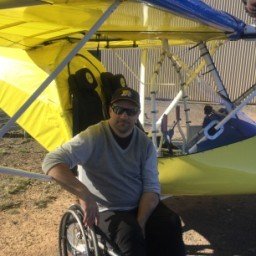
It sure was a great project to build and awesome fun to fly too.
Congratulations @peterg! You received a personal award!
You can view your badges on your Steem Board and compare to others on the Steem Ranking
Vote for @Steemitboard as a witness to get one more award and increased upvotes!