Clap Switch Circuit Using 555 Timer IC | A Tutorial on How to Construct Application of 555 Timer IC Using Fritzing Beta
What Will I Learn?
- Users will learn how to use the 555 timer IC as a switching device for some circuits.
- Users will learn how to draw schematic diagram and breadboard prototype of clap switch circuit using 555 timer IC.
- Users will learn how to construct the clap switch circuit using 555 timer IC on a breadboard.
Requirements
For the users to follow this tutorial, they are required to have the following;
- Fritzing beta software
- 1 unit of 555 timer IC
- 1 unit of
- 3 units of 2N3904 NPN transistor
- 1 unit of electret / condenser microphone
- 1 unit of 74LS74N (Dual flip-flop IC)
- 1 unit of LED (light emitting diode)
- 1 unit of 4.7k ohms resistor
- 1 unit of 470 ohms resistor
- 1 unit of 47k ohms resistor
- 1 unit of 220 ohms resistor
- 1 unit of 0.1 uF electrolytic capaciotr
- 1 unit of 0.01 uF capacitor
Difficulty
- Intermediate
Tutorial Contents
Circuit description
This circuit has an ability to turn off and turn on using the sound produce by clapping of hands. The condenser mic will capture the sound from clapping and it produces a small amount of current base on the magnitude of sound. Then, this current will be amplified using two stage transistor amplifier. This amplified current will be use to trigger our 555 timer IC. The 555 timer IC is connected to make a mono-stable multi-vibrator circuit. This circuit produces a two level of voltage for turn off and turn on. Because we connected it in mono-stable, the circuit's output will be always zero and once the mic receives sound it will trigger the 555 timer to change the voltage level for a couple of seconds. The length of time will be varied by the value of resistor (R2) and capcitor (C1). For last component, I sued 74LS74 IC (D flip-flop) to make the voltage change stable. This will make the output of circuit to change the voltage level whenever it is triggered.

- Condenser Mic
- Two stage Anplifier
- Mono-stable 555 timer IC
- 74LS74 D flip-flop IC
Part A | Drawing Schematic Diagram on Fritzing beta
For the schematic drawing, you may refer to my previous tutorial here for the keen details of drawing schematic.
For this, I will show to you how to draw schematic diagram but, not as detailed as the previous tutorial. I am assuming here that the user already had a background of fritzing beta.
Step 1 | Open Fritzing beta
You can open your fritzing software from your desktop icon or using the start menu and search for fitzing software.
Click the "Schematic" button to open the schematic viewer.

Step 2 | Placing of Component
You can select the components to place from the fritzing image library located at upper right of the window.
If the component was not on display, you can use the search box to find the component.
Select the image to be place and drag it to fritzing workstation.

I will place some components that we need.
Step 3 | Wiring the Component
To wire, place the mouse cursor to the pin of component where you want to wire. Wait for the pin to make it color blue and click the pin. Drag the wire and click again to the pin where you want to connect.

To make the wiring pleasant, you can click the wire and drag it to make a corner.
In schematic diagram standards, we can use only a vertical and horizontal straight line. We cannot use slant line.

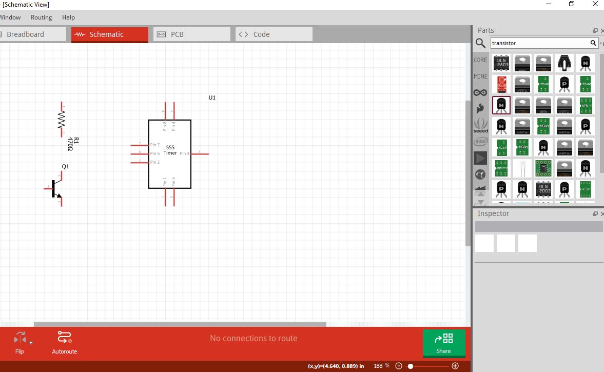
Step 4 | Continue Placing the components
Placing component is the same procedure in Part A; Step 2. For this, let us place all the need components.
These are all the components we need for the circuit.

Step 5 | Arrange the Components
Arranging the components is vital in making schematic. This will be our basis in its appearance and how easy it is to follow during construction stage.
To arrange, we can rotate the components to make it suitable to our design and we can move it by clicking and dragging the component.
This is how I arrange the components.

Step 6 | Continue Wiring the component.
For wiring, you can refer the procedure on Part A; Step 3.
This is the finish drawn schematic diagram

Part B | Making of Breadboard Prototype
Step 1 | Transferring to Breadboard Viewer
Open the breadboard viewer of Fritzing, click the "breadboard" button located at the top of window beside "schematic" button.

This what happened if I click the breadboard button. All the components drawn from our schematic, will be automatically loaded to our breadboard viewer. Broken line between components represents the connection of each circuit.
All lines must be connected.

** Step 2 | Arrange the Component**
Arrangement of the component to our breadboard is all up to you. Use your creativity skills to make the components pleasant to others and easy to connect. Click and drag the component to move and release it to desired location. You can rotate the components to avoid the broken lines tangled to other.
the less the tangled line, the less error in connecting wire.
This is how I arrange my components. You can use my arrangement or you can design it yourself. The broken lines will be your guide on how you will connect.

** Step 3 | Wiring the Components**
When wiring, follow the dash (broken) lines connected between components. These are your guide which components you should wire.
When you click the part where you want to connect, its corresponding endpoint will be highlighted. This will be your hint were where wire must end.


Now, let us wire all the components. We can see that some wires overlap to other wire which made it difficult to follow. To, solve this problem, we will make bend in our wire and change color of wires.

** Step 4 | Color Change and Making Bends (Optional) **
I stated it optional because you can do breadboard prototyping without this features. But this features are helpful especially when you want your prototype looks clean, easy to follow, and in order.
For color change, click the wire and change the color from property box located at right bottom of the screen.
For making bends, click the wire and drag it where you want to make a bend.
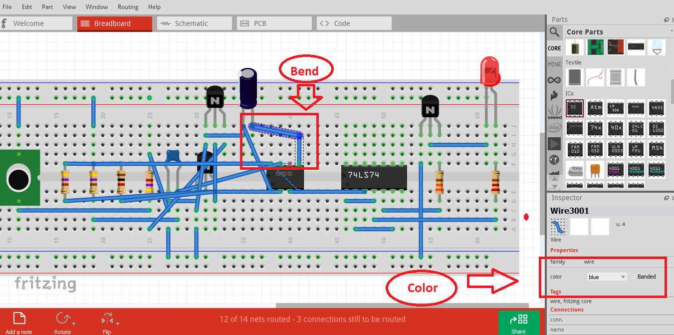
After following the steps, our output will look like this.

Part C | Construction of Circuit to Breadboard
Step 1 | Gather Components
Before constructing circuit, it is best if we gather first all our needed components. Do this to make your work straight. Here is the picture of our components.

Step 2 | Placing Components to Breadboard
After we gathered the component, let us place the components to our breadboard. Because we already had our breadboard prototype, we will follow its arrange to our actual construction.
If some components are hard to pin/mount in the breadboard, use long nose pliers to avoid injury.
Step 3 | Wiring the Components
Use wire stripper to remove the insulator of wire to be inserted to the breadboard. You can also use long nose pliers to insert into breadboard to prevent injury.

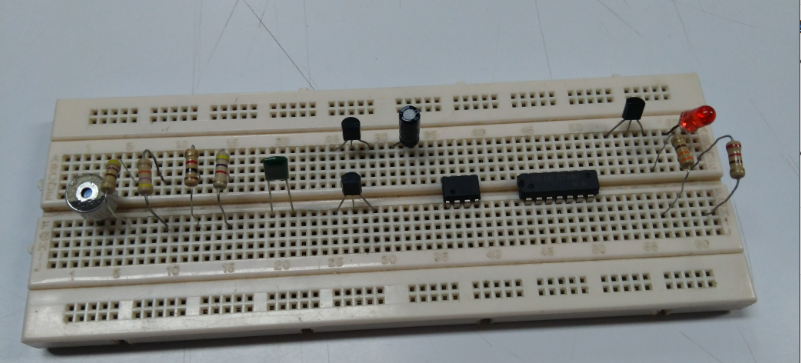
Here is our finish circuit for clap switch using 555 timer IC.

Curriculum
Here are my other tutorials, you can check it out for reference. These tutorials could might help you.
- Tutorial on How to Construct Power Supply Circuit from Schematic Diagram to Breadboard Prototype and to Breadboard Construction.
- EasyEDA PCB Layout | How to transfer your schematic diagram to PCB design in EasyEDA
- How to Create Schematic and PCB Libs in EasyEDA
Posted on Utopian.io - Rewarding Open Source Contributors
This is a test comment, notify @kryzsec on discord if there are any errors please.
Being A SteemStem Member
Your contribution cannot be approved because it does not follow the Utopian Rules.
You can contact us on Discord.
[utopian-moderator]