QUCS Circuit Simulator | How to use Parameter Sweep in Simulation
What Will I Learn?
The users will learn the following:
- You will learn what is parameter sweep.
- You will learn how to operate the parameter sweep feature of QUCS circuit simulator
- You will learn circuit example that needs parameter sweep for its analysis.
Requirements
For the users to follow the tutorial, they will need to have the following.
- Laptop or PC
- Basic knowledge on circuit simulation
- QUCS circuit simulator (can be downloaded at http://qucs.sourceforge.net/download.html)
- Basic knowledge on circuit analysis
Difficulty
- Intermediate
Tutorial Contents
This tutorial aims to teach the users or readers on how to perform a feature of QUCS simulation called parameter sweep. This tutorial also aims to bridge the gap between users of QUCS to the software itself. The simulation function of this circuit simulator is not common from other commercial circuit simulator. QUCS provides separate simulation technique for different circuit types while most circuit simulator provide the same simulation technique with outputs base on the circuit types.
What is Parameter Sweep?
Parameter sweep is a special function in circuit simulation in which the users can set a range value of the component's parameter. For example, for a resistor its parameter is the resistance and the output of simulation will vary if we change the parameter (resistance) of resistor. Using the parameter sweep technique, users will set a range of resistance and will be sweep the parameter value with the given range. So it means, it simulate all the values of resistance with in the pre-determined range of value.
In circuit analysis with the aid of simulation, it is often to do alterations of circuit design the meet the specification or intended output of the circuit. Not only alteration of component which suites the circuit design but also the dimension or parameter of a component. Parameter sweep make the alteration efficient and easy. Instead of altering the parameter one by one and investigating the result individually, parameter sweep will show output with the parameter range. So you can investigate the result of all alteration of parameters.
With Parameter Sweep VS. Without Parameter Sweep
Using this simple circuit, we will compare the result in with and without parameter sweep. Maybe your asking "why I use this so simple circuit?". Well, I represent simple circuit to easily understand the concept. Later on after you understand the concept, then that is the time to have a more complex circuit.
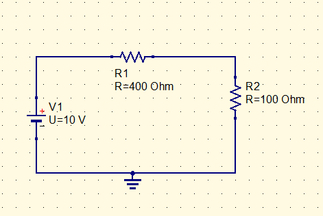
Simulation without parameter sweep.
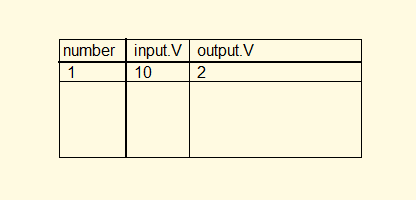
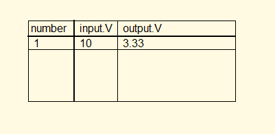
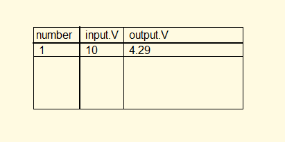
We will simulate the circuit to determine the output voltage of resistor (R2). We will vary the resistance of R2 (100, 200, 300, 400, 500 ohms) and get the output voltage for every resistance value.
For 100 Ohm;
For 200 Ohm;
For 300 Ohm;
For 400 Ohm;
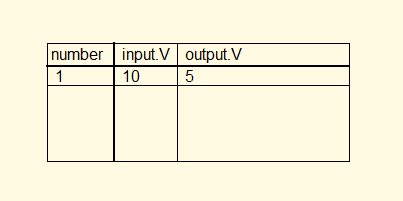
For 500 Ohm;
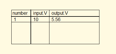
Base on the result, every table shows the output voltage for a given value of resistance. But, it was tabulated individually. Every result needs to generate tables. This is inefficient because we need to simulate again every time we change our resistor parameter or value.
Simulation with Parameter Sweep.
Now we will use parameter sweep to simulate the result with (100. 200. 300, 400, 500 Ohms) value.
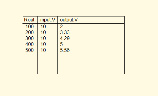
Simulation result using parameter sweep simulate the each resistor value at the same time instead of simulating it one by one. Its is efficient and users can compare the result at the same time.
QUCS Parameter Sweep Simulation.
Now we have seen the difference between them and we know that using parameter sweep is better than simulating it every time we change the parameter value. Again, QUCS simulation function is not totally the same with other circuit simulation software. I will teach you how to do it in QUCS, We will use this circuit to see the action.
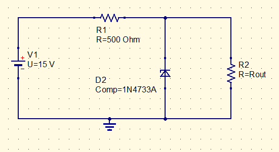
This is a voltage regulator circuit using zener diode. The nominal value(voltage) of this diode is at approximately 5.0 volts. Whenever the voltage across resistor (R2) is greater than 5 volts, it will be regulated. Thus, voltage across resistor R2 will not exceed at 5 volts (it may exceed a little but it is much closer to 5 volts).
Now, we will simulate to determine when does the zener diode starts to regulate the circuit. There are two ways to be able the zener diodeto regulate. (1) vary the value of the value which is the R2. (2) vary the voltage supply which is the V1..
Construction of Circuit.
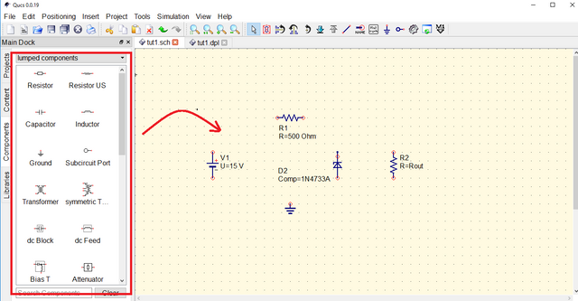
Place the needed components form the QUCS library to our canvas. Click the component from library and click again to the canvas to place. Drag the component from the canvas to transfer its location. Right click to component to see menu in formatting the component like rotate, copy and paste. Double click the component to change the value.
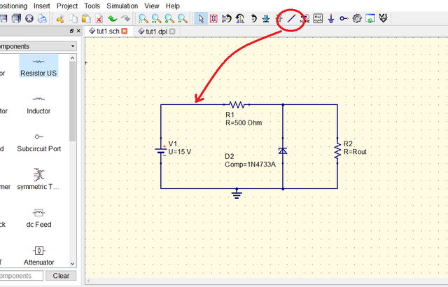
Wire the circuit by using the wire command located at the top of window and near from menu bar. Click the terminal of component where to start wiring and click to another terminal where to end the wiring.
Circuit Simulation
Now, we will choose the appropriate simulation technique for this circuit. Parameter sweep is a just a feature or an add-on to simulation. Thus, parameter sweep is can be use in DC simulation, AC, simulation or Transient simulation. Because it is a DC circuit, we will use the DC simulation as our primary simulation process.
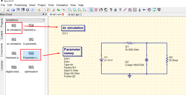
Varying Load Resistance
We will simulate first the zener diode regulation by varying the resistor of the load or the resistor R2. Therefore, we will not assign resistance value of R2 because in our simulation it is not fix value and it is varying. Instead I labeled it with "Rout" which means Resistance for output. But you can label it with what you want.
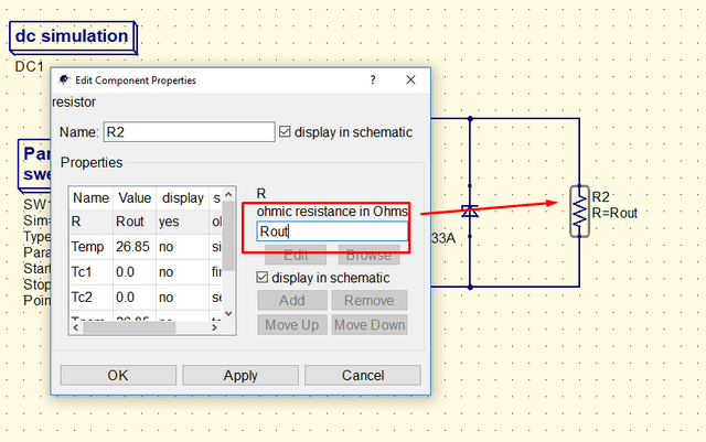
We will set the settings of our parameter sweep. Double click the Parameter Sweep on the canvas to show a dialog box for parameter sweep settings.
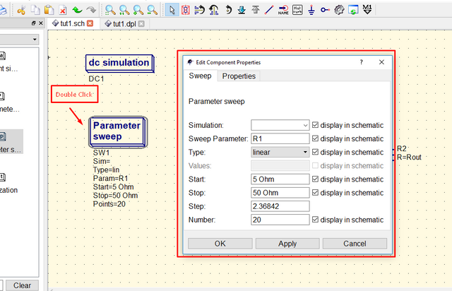
Here are the tips on what to input to the parameter sweep settings.
- Simulation - use DC1 because we are using the DC simulation. DC1 is also the label for our DC simulation.
- Sweep Parameter - we will determine what parameter we want to sweep. Because we are varying the value of R2, this is the parameter we need to sweep. Because we did not assign value to R2 and we just label it with "Rout", use Rout to input in our sweep parameter box. Do not use R2 because it will cause an error in simulating.
- Type - it is how the range of value be inputted.
- Start - it is the starting value of parameter to sweep. We will start from 0 Ohm to cover the value of less than 1.
- Stop - it is where the value of parameter to end. After this, simulation will also stop. It is up to you where you stop the sweep. In this case I use 1000 Ohms because I think with this range I can get my result clearly.
- Step - it is the increment of the parameter.
- Number - it is the number of division for our parameter sweep range. Step and Number is related. Changing the step will change the number.
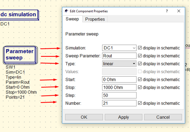
Input the settings appropriate to your simulation and click apply and OK.
Use Wire Label command to label the part to simulate. I label it with input and output to determine where is the input and output of our simulation. Save the file and simulate.
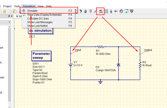
After simulating, other canvas tab will appear for our simulation result.
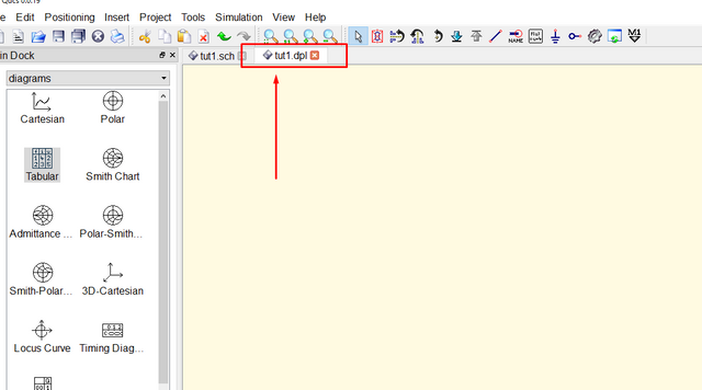
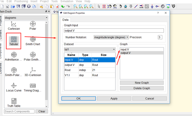
Now, we will choose a diagram to display the result of our simulation. For this I will choose "Tabular" to display the result. I have my other tutorial on how to use the different simulation techniques and simulation diagram to display the result. I posted the link at the button part of this tutorial.
Click the "tabular" and click again to our canvas. A setting of tabular will show. Double click the area where you want to display the result in tabular form. For this, I want to see the output with is corresponding input, so I will choose input and output. Click apply and Ok.
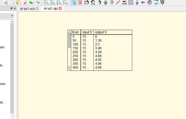
This is the result.
To make the table bigger and see all the result, click the edge of the table and drag it.
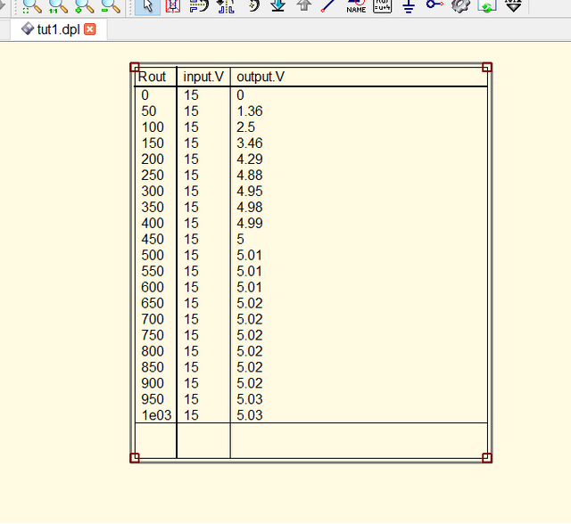
Base on the result, the approximately at 400 Ohms the zener diode started to regulate the circuit. Further increasing the resistance, it has a very small increment of voltage.
Varying Input Voltage
Now, let us simulate the circuit with the voltage as the parameter to sweep. Change the label of our input voltage as Vin because we can not do parameter sweep if we fix the value to be parameterize.
Change the setting of the Parameter Sweep in the dialog box.
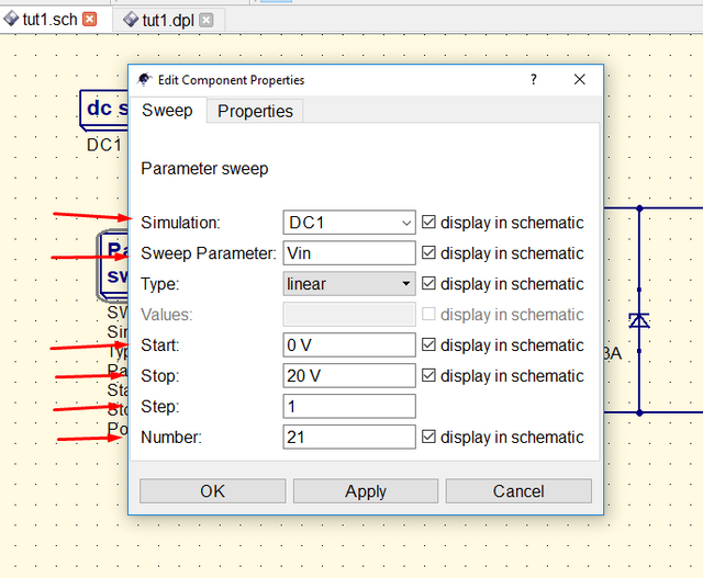
Here is the result of simulation.
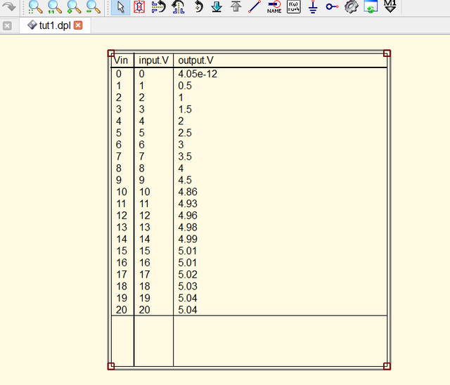
Base on the result, regulation started with input voltage approximately at 10 V. After 10 V, there is a little increment of the output voltage.
Curriculum
Here are my other tutorials in QUCS circuit simulator.
- Understanding Thevenin Theorem | A circuit theorem explained with the aid of circuit simulator
- Understanding Zener Diode | Investigating How Zener Diode can be Use as Voltage Regulator
- How to Use the Different Simulation Scheme of QUCS Circuit Simulator
Posted on Utopian.io - Rewarding Open Source Contributors
Thank you for the contribution. It has been approved.
You can contact us on Discord.
[utopian-moderator]
Thank you @deathwing
Hey @deathwing, I just gave you a tip for your hard work on moderation. Upvote this comment to support the utopian moderators and increase your future rewards!
Congratulations! This post has been upvoted by the communal account, @steemph.cebu by thinkingmind being run at Teenvestors Cebu (Road to Financial Freedom Channel). This service is exclusive to Steemians following the Steemph.cebu trail at Steemauto. Thank you for following Steemph.cebu curation trail!
Don't forget to join Steem PH Discord Server, our Discord Server for Philippines.
datua na nimo sir oy!
di gihapon ko kaapas sa kadatu nimo kim
Ok, it has been approved!
@portugalcoin.. my contribution is not addressing circuit design or it build an electronic module.. my tutorial is about how to use parameter sweep in simulation, it is a featute that qucs offered.. I just use a circuit as an example on how to use it (it can not be done w/o circuit example coz qucs is a circuit simulator).. if we read the content, it teaches how to use a feature of a software.
Hi, we evaluated your work again and you are right. @portugalcoin was not online but we will let him know.
@espoem, thank your for reviewing again..
Hey @thinkingmind I am @utopian-io. I have just upvoted you!
Achievements
Community-Driven Witness!
I am the first and only Steem Community-Driven Witness. Participate on Discord. Lets GROW TOGETHER!
Up-vote this comment to grow my power and help Open Source contributions like this one. Want to chat? Join me on Discord https://discord.gg/Pc8HG9x