How to Use the Different Simulation Scheme of QUCS Circuit Simulator
What Will I Learn?
In this tutorial, the users can learn the following:
- Users will learn the different simulation scheme used in QUCS simulator.
- Users will learn what type of simulation scheme is appropriate for an specific circuit.
- Users will learn how to use the simulation output diagrams in QUCS simulator.
- Users will learn what type of output diagram is appropriate for specific simulation scheme.
Requirements
For the users to follow the tutorial, they are require to have the following:
- PC or laptop
- QUCS Circuit Simulator Software ( can be downloaded at https://sourceforge.net/projects/qucs/)
- Basic Knowledge on Circuit Analysis
- Basic Knowledge on Circuit simulation ( If it is your first time, it is also okay. I encourage to try other simulator software see the differences)
Difficulty
- Intermediate
Tutorial Contents
This tutorial aims for the users of QUCS circuit simulator on how does its simulation works. As for me, simulation in QUCS is very different from other software. Some software used "Play" button to start simulation. Others also just click "simulate" to start. In case of QUCS, it is not easy as that. There are many pre-defined settings before starting.
To my experience, I took time before I fully understand QUCS process of simulation. I read the QUCS help system in its help section, but I did not fully understand, it was not fully stated in details. It is easy in the text but, hard to do.
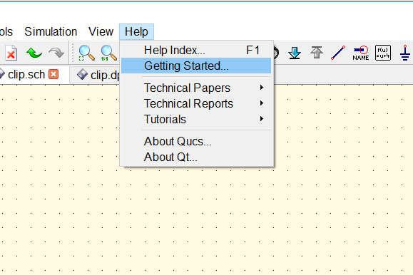
Here the picture of QUCS help section.
This tutorial will be a guide for users who have difficulty in using its simulation.
QUCS available simulation scheme
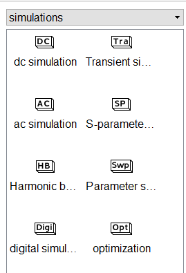
For this tutorial, I will explain how to use these common simulation scheme. These are:
- DC Simulation
- AC Simulation
- Transient Simulation
Why I only focus on these? Because these are the common and fundamental simulation scheme. If the users will master on it, they can also do the same thing for other simulation scheme.
DC Simulation Scheme
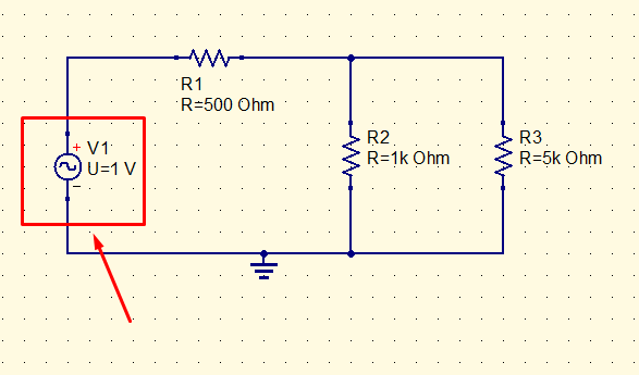
This simulation scheme is intended to simulate DC circuits. To know if the circuits are in DC form, look for the power sources available. If it uses DC voltage or DC current as a source, then DC simulation should be use. Otherwise, you can not use DC simulation.
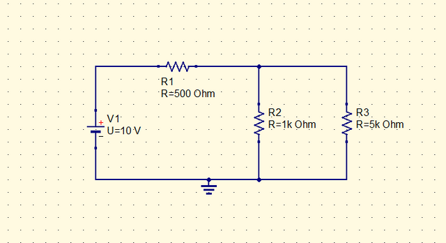
I have here a sample DC circuit. This circuit will be use for the simulation.
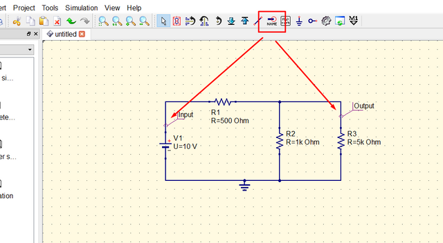
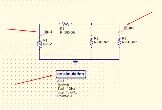
For every simulation scheme wire labeling is needed before starting simulation. The "wire label" command will serve as the simulation point. It means that it is the part of the circuit that must be visualize through simulation. To use it, click the wire label command and click the point on the circuit to be simulated. Name the label to give identify (ex. input, output)
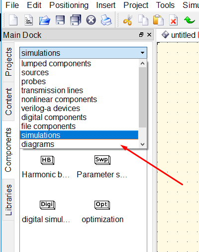
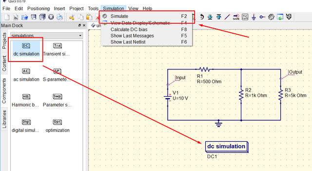
Then select the DC simulation. It is located at the right side of the panel.
Place the "DC Simulation" and click "simulate" on the simulation menu. I assumed that the project was already saved. I will not simulate when the project was not saved.
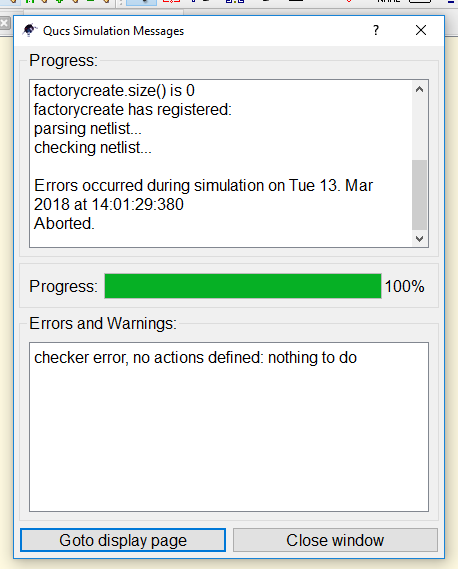
A dialog box will appear showing the simulation process. If there was wrong with simulation, it will be stated in the dialog box the problem. In this case, there was no problem and simulation 100%.
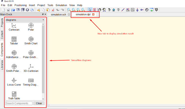
After the simulation, new tab will be created. This tab will be used as a window to place our simulation result. Simulation diagrams will also be available. These diagrams will be used to display our the result simulation process. DC simulation, the appropriate diagram to use in table. It will show results in tabular form. The rest is not appropriate for DC simulation.
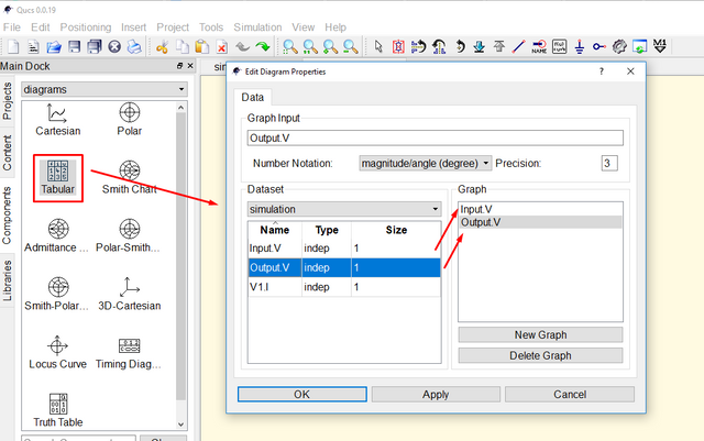
So, we will try displaying the result in tabular form. Place the table diagram by clicking and dragging to the work area. Dialog box will pop-up to change the parameters of the table. For this, I will display the input and the output of the circuit by double-clicking the input and output label. As you see, the graph portion of table will be filled with input and output. Then, click apply and ok.
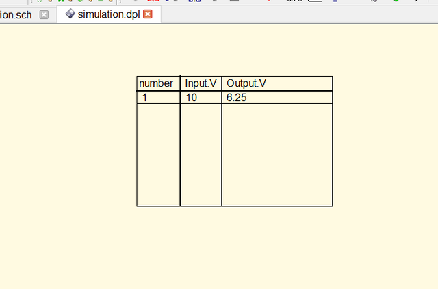
Then it was the result of the simulation. For in of 10 V, the output voltage is 6.25 V.
AC Simulation
To identify the circuit if it was in AC form, look again for the supply voltage or supply current. If it has AC voltage or current source, then it is AC. If two source are available (AC and DC), use the AC Simulation Scheme.
We will consider this circuit as an example.
Do the same process before starting the simulation as stated above. Make a wire label and select AC simulation to perform AC simulation process. Save the file and then click simulate from simulation menu.
The display the result, we will use Tabular and Cartesian. We will consider first the tabular diagram and see the result.
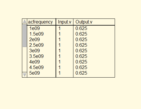
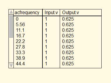
As we see in the result in tabular form, the "acfrequency" values are 1e09, 1.5e09, 2e09 and so on. 1e09 means 1 to the exponent of 9 or equal to 1,000,000,000. It started from 1,000,000,000 Hz or 1 GHz because the parameters of our circuit starts from 1 GHz. We will try to change the value of it.
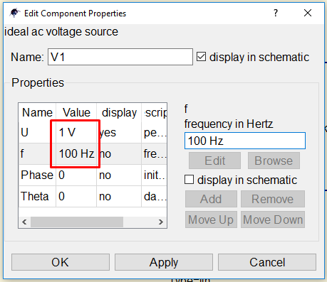
Double-click the supply voltage and a dialog box will appear to change the parameters. Change the frequency of supply voltage from 1 GHz to 100 Hz, 1 V to 10 V.
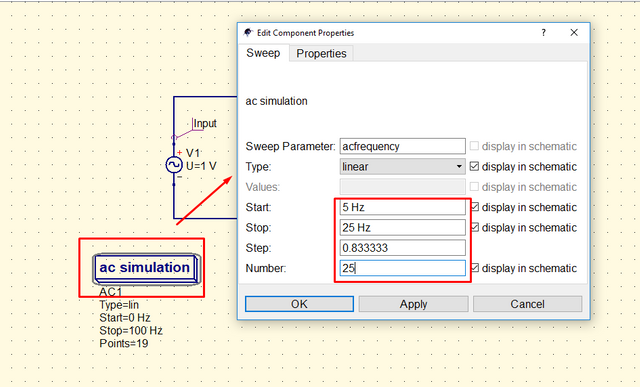
We will also change the parameters of AC simulation. Because our supply has 100 Hz, we will start simulation from 0 Hz to 100 Hz. Double-click the "ac simulation" and a dialog box will pop-up to change parameters.
To change the resolution of our simulation result, change the "step" or "number" in AC simulation. Changing the resolution is like seeing the results more clearer, more specific, more detailed. To change the resolution, Double-click the AC simulation and change the parameters. We will try to see the result from 5 Hz to 25 Hz, change the number to 25. It means that the frequency between 5 and 25 Hz will be divided into 25 parts and will get the result in every 25 parts.
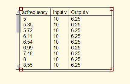
Here's the result.
Now, we will try to show results using Cartesian. Do the same steps in Table diagram.
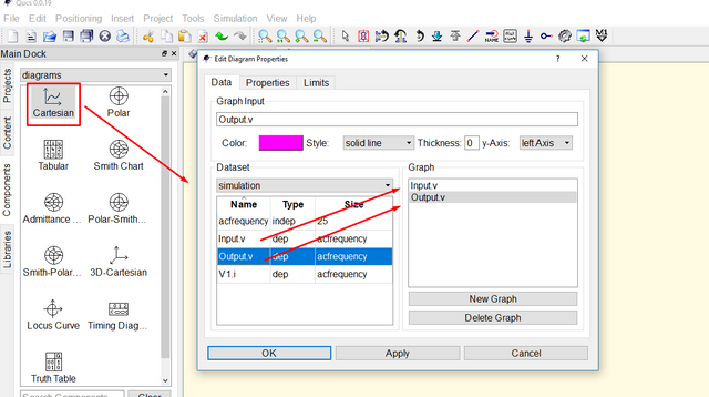
This is the result. I use two diagram to separate input and output.
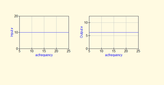
We notice that the graph shows a straight line and we don't see a sinusoidal waveform. If we wish to see the sinusoidal waveform, use the transient simulation to see the changes in a graph
QUCS simulation does not offer a real time simulation. Real time simulation shows the result in running frequency mode or shows result in an instant time. That is why we need to change the start and stop of ac simulation to see result from specific frequency.
Transient Simulataion
Transient is the period of time a circuit changes its mode to another mode. Transient analysis studies how the circuit behaves when it changes from different mode (ex. from on to off).
For transient simulation, we will consider the same circuit before.
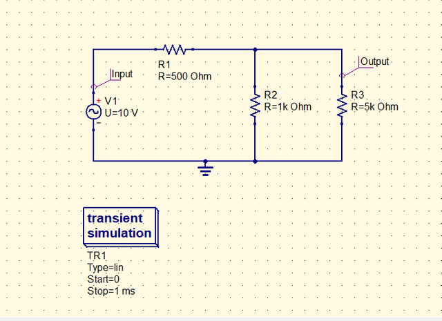
Click the simulation to start. For transient simulation the best diagram to use is the Cartesian to see the changes from time to time. Here is the result.
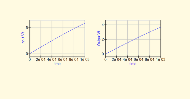
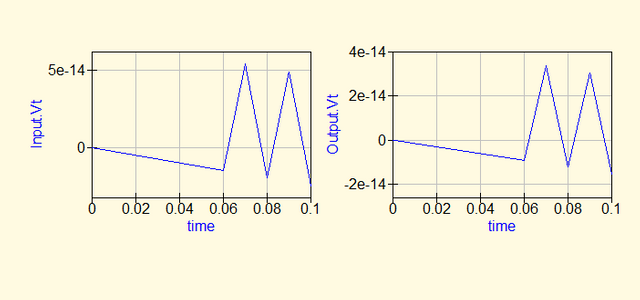
The result shows a ramp figure instead of sinusoidal. This is because the resolution is very high and we only see the going up graph of a sinusoidal wave. So, will try to change the parameters of transient simulation. We will change the stop time from 1 ms to 100 ms.
Here is the result.
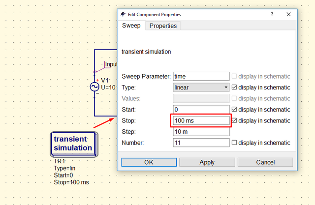
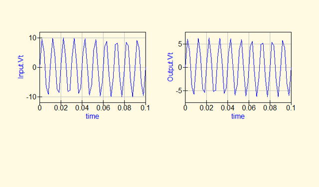
To see the clearer picture of sinusoidal wave, we will increase the division of the period/time. We will change from 11 to 50. Here is the result.
Now, we will decrease the period of graph to focus on the small part of the wave. We change from 100 ms to 20 ms. Here is the result.
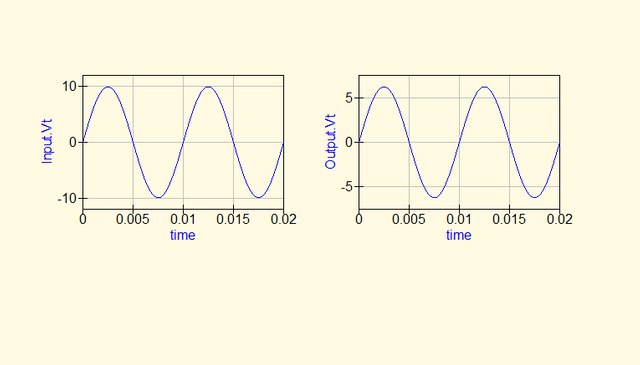
The sinusoidal wave is now clear enough to observe. Change the parameter of simulation to have a clear view to the graph. This will give you a more precise observation on the circuit behavior.
Curriculum
Here are my other tutorials, you can check this out for reference. This might could help you.
- Tutorial on How to Construct Power Supply Circuit from Schematic Diagram to Breadboard Prototype and to Breadboard Construction.
- EasyEDA PCB Layout | How to transfer your schematic diagram to PCB design in EasyEDA
- How to Create Schematic and PCB Libs in EasyEDA
- Understanding Thevenin Theorem | A circuit theorem explained with the aid of circuit simulator
- Understanding Zener Diode | Investigating How Zener Diode can be Use as Voltage Regulator
- How to Give Solution to a Problem using Logic Circuit
Posted on Utopian.io - Rewarding Open Source Contributors
Thank you for the contribution. It has been approved.
You can contact us on Discord.
[utopian-moderator]
Thanks @ruah
Hey @ruah, I just gave you a tip for your hard work on moderation. Upvote this comment to support the utopian moderators and increase your future rewards!
Congratulations! This post has been upvoted by the communal account, @steemph.cebu by thinkingmind being run at Teenvestors Cebu (Road to Financial Freedom Channel). This service is exclusive to Steemians following the Steemph.cebu trail at Steemauto. Thank you for following Steemph.cebu curation trail!
Don't forget to join Steem PH Discord Server, our Discord Server for Philippines.