Diode Rectifier| a circuit simulation of full-wave rectifier and a step by step tutorial how to simulate full-wave rectifier circuit using Multisim (Analog Devices Edition)
Good day! This is my second tutorial on electronics devices. My first tutorial was about how to check the condition of a diode. Now, it is more on the application of diode. Check my tutorial and open your mind on the magic of electronics. Hope you like it.
This tutorial focuses on a single application of diode which is the full-wave rectifier. There are two types of rectifier circuit (half-wave and full-wave) but, I choose full-wave rectifier because it is often used especially the bridge type one (which I will be constructing). Let me share to you what is a full-wave rectifier before we proceed to the simulation of circuity.
This circuit is suitable for low power applications and applications that needed steady supply voltage or what we known as DC supply voltage. Full wave rectifier produces a voltage which has a specified DC component, or shall we say converts AC to DC voltage or current supply.
This is what a AC waveform look like

This is what a full-wave rectified waveform look like. It will be the output if an AC waveform is fed into the full-wave rectifier.

Rectifier works like a one-way valve, allowing only half portion of the waveform and the output
waveform is called as a pulsating DC. This waveform can then be filtered to remove the unwanted variations. The three basic rectifier circuits are the half-wave, the center-tapped full-wave, and the full-wave bridge rectifier circuits.
Let us begin the simulation!
1. Introduction
To begin with Multisim, let us identity the basic parts or commands of Multisim.
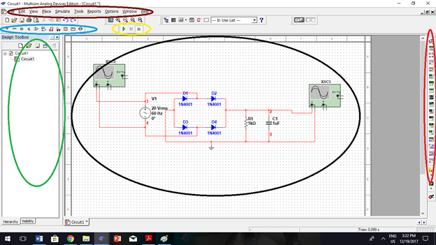 Components (Blue) – this is where you can select components for your schematic diagram
Instruments (Red) – this is where you can select instruments (multimeter, oscilloscope, function generator, etc.) to visualize the simulated instrument
Simulation (Yellow) – if you are ready for an interactive simulation, you can press “play” to begin simulation and “stop” to end simulation
Drop down Menu (Brown) – this is where you can find menus you can use for simulation
Work area (Black) – it is where you place and construct your circuitry to be simulated.
Circuit panel (Green) – the area where you can find the circuit you have constructed.
2. Selecting of Components.
Circuit simulation in Multisim begin by placing or drawing the schematic diagram into the Multisim environment. Here are some examples o how to place your components on the Multisim.
Selecting Diode. Locate the components area and click place diode (as seen in the picture). Select diode groups and choose the diode that you will use.

Selecting Capacitor. Locate the components are and click place basics (as seen in the picture). Select capacitor groups and choose the capacitor that you will use.

3. Wiring the schematic diagram.
Multisim has the functionality of mouse pointer by the position of mouse. You can simply do wiring the schematic by clicking and dragging of your mouse. Follow the steps below for wiring schematic.
- Move the mouse pointer at the pin of a component. The mouse pointer will change into a crosshair instead of default mouse pointer.
- Click the pin of the part of a component to place an initial wire junction.
- Move the mouse to another terminal to complete the wire.

4. Circuit simulation.
When your schematic diagram is ready to simulate, place an instrument that visualize your simulation. You can choose any kind of instrument seen of the instrument button. Click the play button and start the simulation.
I have here a constructed full-wave rectifier circuit and I will simulate it.
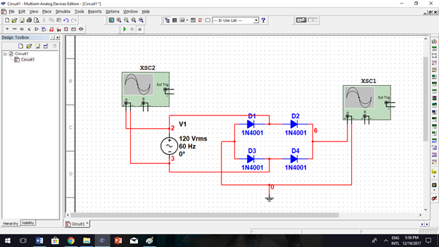
As I run the simulation, the oscilloscopes visualize the waveform. Right graph(input), Left graph(output)

Now, I will put a filter circuit after the rectifier circuit. The filter will remove the DC variations and will results to more stable DC output.

In the picture above, I used capacitor with 50uF value. The higher the value of capacitor, the output is more stable. I changed the value to 1000uF and this is the result.

You can change the value of capacitor, resistor, and diode according to your desired output. But, don't forget to refer to the data sheets of components to ensure effectiveness and compatibility of your circuit.
Hope you like my tutorial and enjoyed it. I am very much open to suggestion if there is something you want to add. Just let me hear it.
thank you!
got some tips in (you can check it out for more on how to start multisim)
http://www.ni.com/white-paper/10710/en/
Posted on Utopian.io - Rewarding Open Source Contributors
Sir butangi ug reference sa kung asa nimo nakuha ug gigamitan nga info. 😁
Your contribution cannot be approved because it does not follow the Utopian Rules.
Contributions on repositories that had no updates for longer than 1 year, will be rejected.
You can contact us on Discord.
[utopian-moderator]