Arduino 101: Tilt Sensor with Arduino
Good day everyone,
Today, we will be learning how to make a tilt sensor using an Arduino Uno board and a Tilt Switch. I assume that by now, you already know a bit about what an Arduino board is. So, this topic today will be very easy for you to follow.
This type of circuit is used in things that needs to maintain its balance, its basically a must have circuitry for them, just like in airplanes, they must have a tilting sensor so that the pilot can know if they are over tilting or not. The information that this circuitry gives can provide safety travel for the people on board the plane
Now that we know how important a tilt sensor can be, let us discover what a tilt sensor is and what its made of.
What is a Tilt Sensor?
A Tilt Sensor ( also known as Tilt Switch or Rolling ball sensors or Mercury switches ) is a component that detects the orientation of the object, it can be the horizontal and vertical orientation or its inclination.
The working principle of this type of component is that, if the sensor is upright the switch is turned ON, it will act as a short circuit, this lets the current (or free electrons) to flow right through the whole circuitry.
While on the other hand, if the sensor is tilting sideways the switch is turned OFF, it will act as an open circuit, this will not let any current pass the circuitry.
There are two kinds of a Tilt Switches
Mercury Switches - This are a type of Tilt switch that uses a drop of mercury in the tube. Once there is a change in the orientation of the sensor it causes the mercury to roll in the tube until it reaches a certain angle that it touches both the contacts which closes the switch. The current will then be able to pass through it.
Image source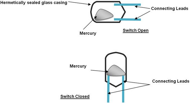
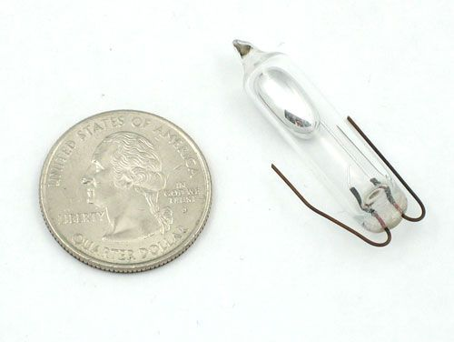
This is the actual look of the Mercury Switch, the mercury is present inside the tube and there are two connecting leads that are separated from each other. It is a very small device as you can see in the picture.
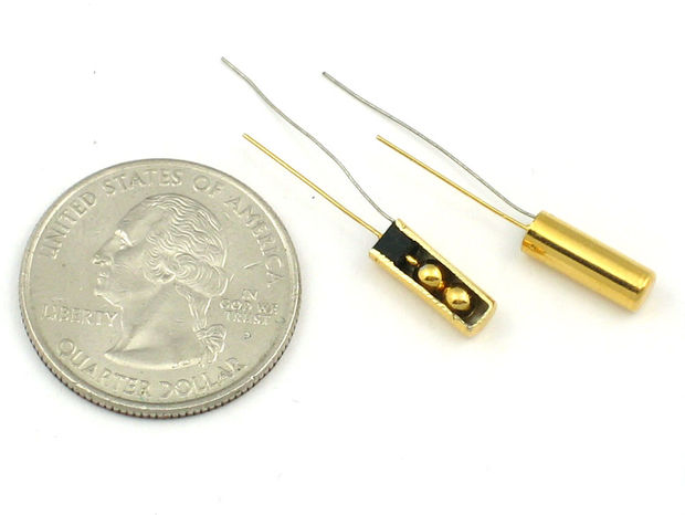
The other type of Tilt switch is the Ball-in-Cage switch. This type of tilt switch uses a small metal ball rather than mercury, It is held in a small housing unit with two or more connecting leads. It works the same way as the mercury switch but uses a metal ball instead.
Image source

This is what the Ball switch looks like in real life, It is also very small like the mercury switch is.
Mercury switch vs. Ball switch
Before, mercury switch was popular and was used by many because of its own benefits, its blob is dense enough that it doesn't bounce making it immune to vibrations. But now, it is rarely used because of the fact that mercury is extremely toxic and lethal. On the other hand, Ball sensor is very easy to make, they will not shatter because of its solid housing and more importantly it does not pose any toxic substance like a mercury switch can. It also does it job but they are more sensitive than the mercury because the ball would bounce during vibrations.
Testing the Switch
In our test today, we will be using a ball switch because it is much safer and more common than the mercury switch.
To test the switch, we connect the digital multimeter probes to the connecting leads of the ball switch and we tilt it upwards. Then set the multimeter to a continuity checker, this will beep if the circuit is shorted.
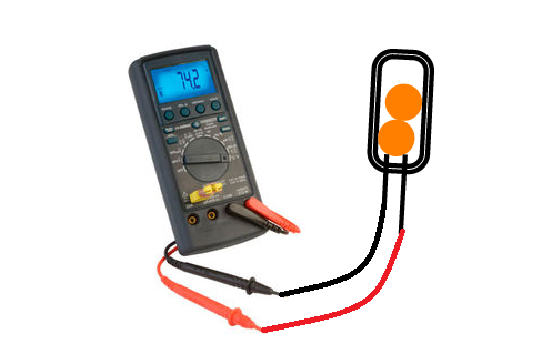
In the picture, you can see that the ball is touching the connecting leads. This indicates that the switch is closed meaning it will let the current pass through it.
Now, we tilt the switch to a horizontal direction.
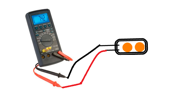
In the picture, you can see that the ball is not touching the connecting leads. This indicates that the switch is open meaning it will not let the current pass through it.
Now that we have finished testing the switch, let us connect it to the Arduino uno.
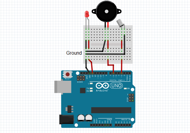
So, we connected the tilt switch to the Arduino uno with a buzzer to make it more awesome. Don't be confused about the black wires, they are ground wires that are connected to the ground or the negative terminal and the red wires that are connected to the positive terminal.
In this circuit, we connected the tilt sensor to pin 3 of the Arduino uno and the other terminal to the ground. The buzzer and the LED are there to serve as the indicator. They will be notifying you that there is an inclination.
The buzzer is connected to pin 6, this is controlled by the PWM output of the arduino which will cause it to generate different tones once activated.
The anode of the LED is connected to pin 13 of the Arduino while the cathode is at the ground pin. I did not put a current resisting resistor to protect the LED from over current because the Arduino only has 20mA( milliamperes ) of current, so it is okay to connect the LED directly to the arduino and also the arduino board has an internal pull up resistor in which you can turn on by setting the input pin to HIGH output.
Programming
Now that we have finished constructing our circuit, let us connect our Arduino to the computer.
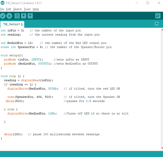
Open up your Arduino IDE, then type in this codes.
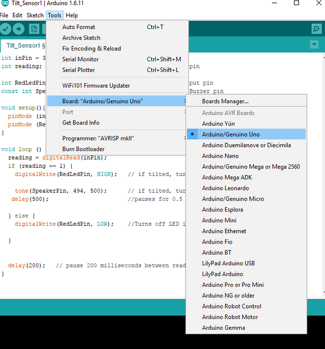
Make sure that you have selected the type of arduino board that you are using, you can set it by going to Tools > Board > then choose your board (i.e. Arduino/Genuino Uno) in this experiment we used an arduino uno , so the arduino uno board is selected.
After you have typed the codes in your IDE, click Verify to check for errors > Upload to your Arduino board, make sure to connect your arduino board to the computer using a usb cable b-a.
After that your circuit should be working. Tilt it sideways to activate the buzzer and LED and tilt it upwards to turn it OFF.
So, that it all for today. I hope you find this tutorial to be useful.
Until Next time!
ted7
signing out,
Oh! I almost forgot, here's the code for easy reading and you can copy and paste it to you Arduino IDE.
                                                          //start of program
int inPin = 3;                              //Establishes the number of the input pin (tilting sensor)
int reading;                                //Establishes the current reading from the input pin (tilting sensor)
int RedLedPin = 13;             //Establishes the number of the Red LED output pin
const int SpeakerPin = 6; // Establishes the number of the Speaker/Buzzer pin

void setup(){
  pinMode (inPin, INPUT);                   //This will set inPin as INPUT
  pinMode (RedLedPin, OUTPUT); //This will set RedLedPin as OUTPUT
}

void loop () {
  reading = digitalRead(inPin);      //This will read the output from the inPin(tilt sensor)
  if (reading == 1) {                               //If the reading is 1 or True it will process the codes under it
    digitalWrite(RedLedPin, HIGH);   // if the tilt sensor is tilted, it will turn the red LED ON

    tone(SpeakerPin, 494, 500);      // if the tilt sensor is tilted, turn the Speaker ON
   delay(500);                       //pause for 0.5 seconds

  } else {
    digitalWrite(RedLedPin, LOW);    //Turns off LED if no there is no tilt

  }
  delay(200);   // pause 200 milliseconds between readings
}
                                                           //end of program
Posted on Utopian.io - Rewarding Open Source Contributors

Thank you for the contribution. It has been approved.
You can contact us on Discord.
[utopian-moderator]
Thank you very much ;)
Hey @ted7 I am @utopian-io. I have just upvoted you!
Achievements
Suggestions
Get Noticed!
Community-Driven Witness!
I am the first and only Steem Community-Driven Witness. Participate on Discord. Lets GROW TOGETHER!
Up-vote this comment to grow my power and help Open Source contributions like this one. Want to chat? Join me on Discord https://discord.gg/Pc8HG9x
Thanks for sharing that. Im looking forward to seeing more Arduino information on Steemit.