Arduino 101: PIR based burglar alarm with Piezoelectric buzzer and Arduino
What Will I Learn?
- You will learn how digital input and output works by using the PIR sensor as the input and the piezo buzzer as the output.
- You will learn how to program the arduino board by using the Arduino IDE.
- You will learn to construct your very own security alarm system.
Requirements
Hardware


Software
- Arduino IDE (Integrated Development Environment)


Knowledge
- Basic electronic and programming knowledge
Difficulty
- Basic
Project description
This project uses an Arduino Uno to control the whole circuit. A PIR (Passive Infrared) sensor as its input device which will detect any movement from the surrounding. Once movement has been detected it will immediately send an electric impulse to the arduino board which will then activate the output device which is the piezoelectric buzzer to sound its alarming sound.
Component description:
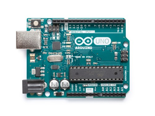
Arduino Uno is a type of arduino board that is the most commonly used, it is packed with a microcontroller board that is based on ATmega328P with 14 digital I/O pins (6 of which are PWM outputs), 6 analog inputs, a 16 MHz quartz crystal and a USB port terminal, a power jack, an ICSP header and a reset button.
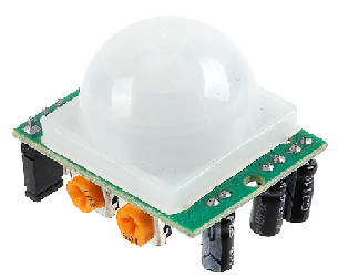
PIR (Passive Infrared) sensors are an electronic sensors that are capable to detect infrared light that are invisible to the naked eye, it measures infrared(IR) light that is radiating from objects within its field of view.
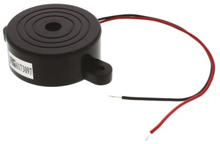
Piezoelectric buzzer is a speaker that uses the piezoelectric effect to generate sound, it can be driven by an oscillating electronic circuit or any other signal source.
Tutorial Contents
Step 1: Gather your parts
- In this project, we will be using common components that can easily be purchased at your nearby electronics shop.

Step 2: Construct the circuit
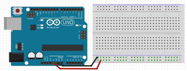
Connect the Sources
- Connect the black jumper wire to the GND pin of the arduino to the ground(-) grid of the breadboard.
- Connect the red jumper wire to the 5V pin of the arduino to the positive grid(+) of the breadboard.
- Note: Make sure not to put the same jumper wires in the same row to avoid short circuiting your arduino board.

Connect the Sensor
- Connect the positive terminal of the PIR sensor to the positive grid of the breadboard.
- Connect the negative terminal of the PIR sensor to the ground grid of the breadboard.
- Connect the signal pin of the PIR sensor to digital pin 4 of the arduino board.

Connect the buzzer
- Connect the red wire of the piezoelectric buzzer to pin 10 of the arduino board.
- Connect the black wire of the piezoelectric buzzer to the GRND pin of the arduino board.
- Note: You can also reverse the placement of the wires if you want because the polarity of the buzzer does not matter.

Step 2: Programming the arduino
Now that the circuitry is constructed, let us now program the arduino uno board.
Open the Arduino IDE in your computer, if you have not installed it yet, click on this link to download and install the file.
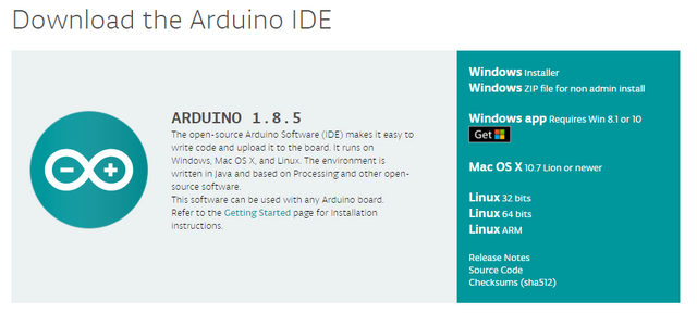
Once installation is complete, launch the software.

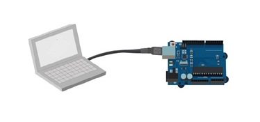
Connect the Arduino Uno board to the computer using the type a to b usb cable.
After the arduino board has successfully connected, go to Tool > Board > then select Arduino/ Genuino Uno.

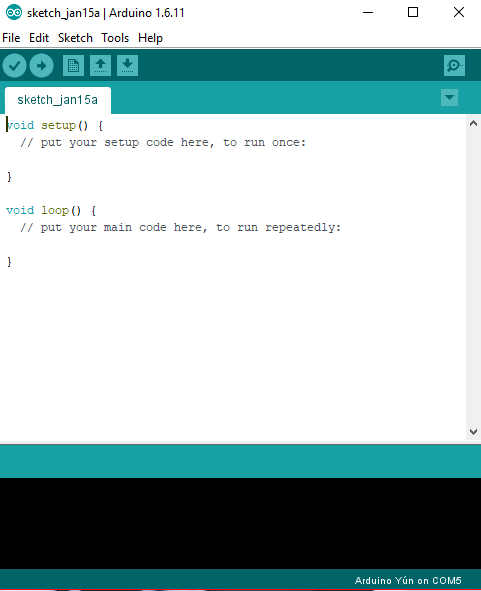


- Now that Arduino Uno is set in the arduino IDE, copy this code into your sketch.
int inputPin = 4;               // The input pin of the PIR sensor

int pirState = LOW;             // initially, we assume that there is no motion detected

int val = 0;                    // variable for reading the pin status

int pinSpeaker = 10;            // The buzzer on PWM pin 10

void setup() {

pinMode(inputPin, INPUT);     // declare sensor as input

pinMode(pinSpeaker, OUTPUT);

Serial.begin(9600);

}

void loop(){

val = digitalRead(inputPin);  // reads the input value

if (val == HIGH) {            // checks if the input is HIGH

playTone(300, 160);

delay(150);

if (pirState == LOW) {

// we have just turned on

Serial.println("Motion detected!");

// We only want to print on the output change, not state

pirState = HIGH;

}

} else {

playTone(0, 0);

delay(300);

if (pirState == HIGH){

// we have just turned of

Serial.println("Motion ended!");

// We only want to print on the output change, not state

pirState = LOW;

}

}

}

// duration in mSecs, frequency in hertz

void playTone(long duration, int freq) {

duration *= 1000;

int period = (1.0 / freq) * 1000000;

long elapsed_time = 0;

while (elapsed_time < duration) {

digitalWrite(pinSpeaker,HIGH);

delayMicroseconds(period / 2);

digitalWrite(pinSpeaker, LOW);

delayMicroseconds(period / 2);

elapsed_time += (period);

}

}
What this code does is simply assigning the PIR sensor that is connected at pin 4 to be the INPUT device, it will read its value as HIGH or LOW state. Once movement has been detected by the PIR sensor will send an electrical impulse to the arduino board, once the state is HIGH it will then trigger the buzzer that is set as the OUTPUT and the serial monitor will display that there is motion detected. The tone is set to a high pitch that will sound as long as their is movement in the area of view. After their is no more movement in the area, it will then switch the PIR into a LOW state then the serial monitor will display motion ended and the buzzer will stop its alarm.
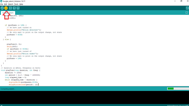
After typing the codes, click Verify to compile the program and check if there is no error.
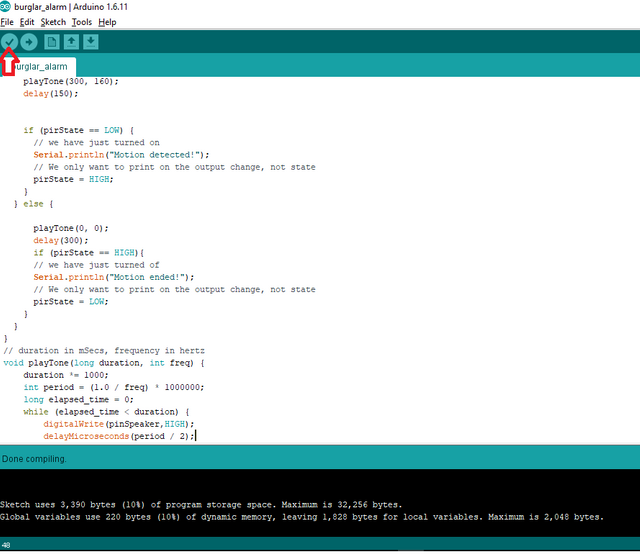
Click upload to install the program into the arduino board.


Step 3: Checking
- Now that all is done, check the circuit if it is working properly. Hover your hand in the field of view of the PIR sensor, if the buzzer will alarm it means its working and if not check the previous steps and look for any errors that you may have done.
Step 4: Placing
After making sure that the circuit is working properly, place it in a place where you want to be secured so that once it there is someone there you will be alarmed.
Now you have your very own burglar alarm, you can also tweak it however you want.
Curriculum
Here are my previous tutorials on the Arduino
- Arduino 101: Tilt Sensor with Arduino
- Arduino Shields
- How to control servo motor using arduino
- Arduino for beginners
Posted on Utopian.io - Rewarding Open Source Contributors
Thank you for the contribution. It has been approved.
You can contact us on Discord.
[utopian-moderator]
Thanks a lot :)
Helpful contribution @ted7
Thank you very much @jbeguna04 :)
nice one. lots of engineering students can learn from this.
Thank you @sabo :)
Hey @ted7 I am @utopian-io. I have just upvoted you!
Achievements
Suggestions
Get Noticed!
Community-Driven Witness!
I am the first and only Steem Community-Driven Witness. Participate on Discord. Lets GROW TOGETHER!
Up-vote this comment to grow my power and help Open Source contributions like this one. Want to chat? Join me on Discord https://discord.gg/Pc8HG9x
nice post