Arduino 101: Force Alarm using FSR and buzzer
What Will I Learn?
- You will learn how a Force Sensitive Resistor works with a Piezoelectric buzzer to create an effective force alarm circuit.
- You will learn how to utilize the arduino uno board to make the FSR and buzzer work together.
- You will learn the programming code for the arduino uno board for this type of circuit.
Requirements
Hardware:
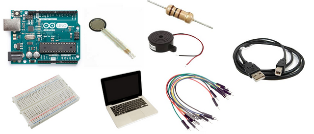
- Arduino Uno board
- Force sensitive resistor
- piezoelectric buzzer
- Resistors (10k ohms)
- breadboard
- Computer
- Usb type A to B
- Jumper wires
Software:
- Arduino Software/ Arduino IDE
Knowledge:
- Basic electronics and programming knowledge
Difficulty
- Basic
Tutorial Contents
- This is a simple project that uses a force sensitive resistor (FSR) and a piezoelectric buzzer. This components are controlled by an arduino uno board, once a force is applied to the FSR's sensor pad, it will then trigger the buzzer to sound the alarm indicating that force has been detected from the sensor.
Component description
Arduino Uno - are type of arduino boards that are used regularly by specialist and hobbyist because of its robust design. It is equipped with a microcontroller board that is based on ATMega328P with 14 advanced I/O pins (6 are PWM outputs), 6 analog inputs, 16 Mhz quartz crystal, a power jack, a USB port, an ICSP header and a reset button.
Force sensitive resistors- are sensors that allows detection of physical pressure, squeezing and weight. They are basically special type resistor that will change their resistance value once force is applied to it. They are easy to use and are cheap.
Step 1: Gather the parts
- The components used are fairly common and should be available in your local electronics shop or you can just order it up online for less hassle.
Step 2: Construct the circuit
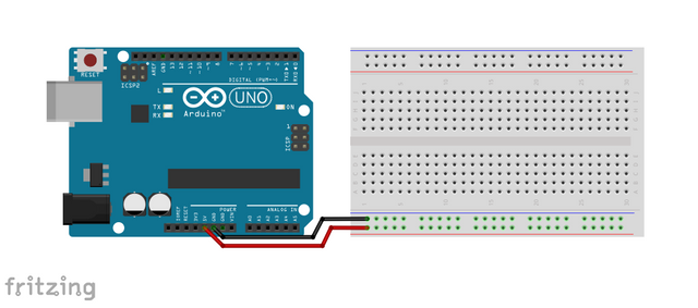
Connect the Sources
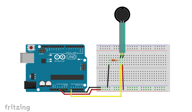
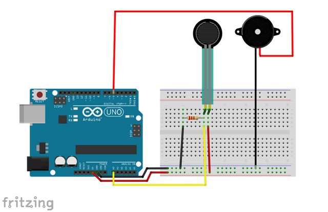
Connect the 5V pin of the arduino uno board into the top/bottom slot of the breadboard. The connections here are horizontally connected making it an ideal spot for the sources.
Connect the GND pin of the arduino uno board into the top/bottom slot of the breadboard but make sure not to short them out to avoid damage to the board.
Connect the Sensor
- Connect one end of the FSR to the voltage source(+) in the breadboard.
- Connect the 10 kilo ohms pull-down resistor to the other end of the sensor and connect it to the ground. This pull-down resistor will help give a reasonable amount of range over the operation of the sensor.
- Connect that same connection to the analog pin (A0) of the arduino uno board.
Connect the Buzzer
- Connect the positive terminal(red wire) of the piezoelectric buzzer to pin number 5 of the arduino uno board.
- Connect the negative terminal(black wire) of the piezoelectric buzzer to the common ground in the breadboard.
Step 3: Programming
Connect the arduino uno board to the computer using a usb cable type a to b.
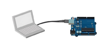
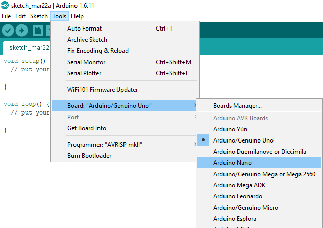
Once connected, open the arduino IDE and go to Tools > Board: > then select the Arduino/Genuino Uno.
- Copy the codes below and paste it to your sketch in the arduino IDE.
int buzzer = 5;   //declares buzzer @pin 5
int FSRanalogpin = A0; //declares the FSR @analogpin A0
int FSRvalue = 0;  //saves the analog value as integer
void setup()
{
pinMode(FSRanalogpin,INPUT); //sets the FSR as the input
pinMode(buzzer,OUTPUT);   //sets the buzzer as the output
}
void loop()
{
FSRvalue = analogRead(FSRanalogpin); //reads the FSR and store it in integer
analogWrite(buzzer,FSRvalue/4); //sets the buzzer duty ratio
}
Code Breakdown
int buzzer = 5;   //declares buzzer @pin 5
int FSRanalogpin = A0; //declares the FSR @analogpin A0
int FSRvalue = 0;  //saves the analog value as integer
This defines the buzzer and the FSR pins and assigned them with variables. The FSRvalue will be the variable used to save the analog values from the sensor.
void setup()
{
pinMode(FSRanalogpin,INPUT); //sets the FSR as the input
pinMode(buzzer,OUTPUT);   //sets the buzzer as the output
}
This code block will be the setup command, where it sets the FSR sensor as the input and the piezoelectric buzzer as the output.
void loop()
{
FSRvalue = analogRead(FSRanalogpin); //reads the FSR and store it in integer
analogWrite(buzzer,FSRvalue/4); //sets the buzzer duty ratio
}
This code block will be the heart of the program, the FSRvalue is set to read the analog values from the FSR and stores it as an integer. Then the analogWrite will control the output of the buzzer. It is set so that the PWM signal will change linearly with the weight of the force being applied to it.
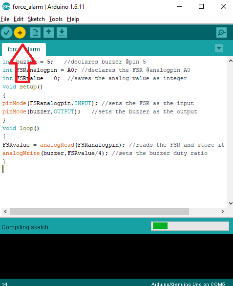
After typing the code in your sketch, click the Verify button to save the sketch and compile it. This will look for any errors in the program.
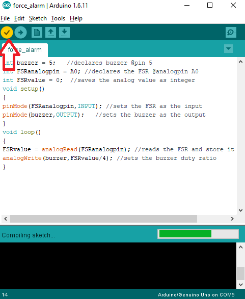
If no errors were found, click the upload button to start the programming of your arduino uno board.
Step 4: Testing
- Once the programming is done, remove the arduino uno from the computer and connect it with a battery pack.
- Once booted, press the FSR sensor pad slightly. This should turn make the buzzer produce sound slightly.
- Now, apply more pressure to it, this should make the buzzer produce louder sound. Because it is set to change its tone linearly as the force increases or decreases.
Curriculum
Below are my other arduino tutorials that you may find interesting.
- Arduino 101: Automated parking gate circuit using ultrasonic and servo motor
- Arduino 101: Using a vibration sensor module (SW-420)
- Arduino 101: Using a KY-036 metal touch sensor
- Arduino 101: Using a Knock Impact sensor (KY-031)
Posted on Utopian.io - Rewarding Open Source Contributors
Your contribution cannot be approved because it does not follow the Utopian Rules.
Violated Rule(s):
My Opinion(s):
You can contact us on Discord.
[utopian-moderator]