Arduino : "Using TCS230 to make Color sensing"
What Will I Learn?
You will learn to use TCS230 module
You will learn how to integrate arduino uno and color sensor TCS230
You will learn how to program arduino uno and TCS230 to create a color sensing
Requirements
Hardware
- Arduino Uno

- TCS230 Module

- Jumper Wires Male To Male

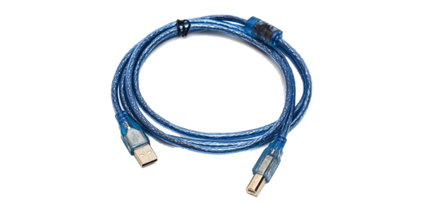
- USB type A to B cable
- Personal Computer (Laptop)
Software
- Arduino IDE

Knowledge
- Electronics and Robotics Basic
Difficulty
- Basic
Project Introduction
Here is an arduino uno tutorial combined with TCS230 color sensor. TCS230 serves as a color reader and removes the color that is read into the LED. When the prototype in the run we simply put something on the sesor object and directly LED issued the same color with the color of the object.
Component Description
Arduino Uno - is a Atmega32-based microcontroller board. Having many digital and analog pins, the arduino can be easily programmed via a computer or laptop with USB and is designed to facilitate electronic users in various fields. As open source he comes with 2 products namely Hardware Arduino Board and Arduino IDE software.
TCS230 Module - is a color sensor that is often used in microcontroller applications including arduino uno for the detection of an object object or color of the objet on the monitor. TCS230 has 8 pin, 2 pin GND (-), 2 pin VCC (+), Pin S0, 1 Pin S1, Pin S2, Pin S3, LED pin, and Pin OUT. The TCS230 senses the color light with the help of an 8 x 8 array of photodiodes.
Tutorial Contents
Step 1 : Prepare All Parts
You can buy from online store or directly to the Electronics Shop

Step 2 : Build Circuit Architecture
- Connect the GND and VCC

- Connect Pin GND Arduino Uno to GND TCS230
- Connect Pin 5V Arduino Uno to VCC TCS230
- Pin Connect

- Connect the "pin number 7" of the arduino uno board to "S2" TCS230.
- Connect the "pin number 6" of the arduino uno board to "S3" TCS230.
- Connect the "pin number 5" of the arduino uno board to "S1" TCS230.
- Connect the "pin number 4" of the arduino uno board to "S0" TCS230.
- Out Connect
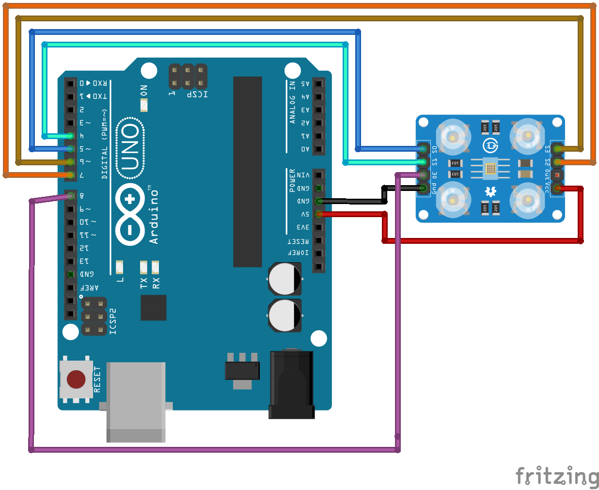
- Connect the "pin number 8" of the arduino uno board to "OUT" TCS230.
Step 3 : Programing
Connect Arduino to the computer with USB .
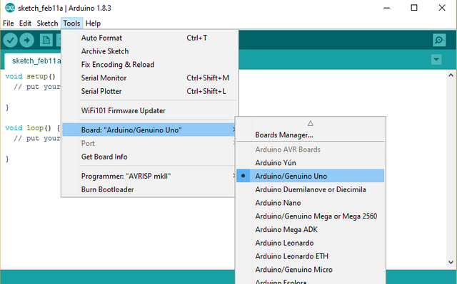
Open the Arduino IDE > Chose your Board Type
first Define Variable
#define

#define SEN0 5
#define SEN1 4
#define SEN2 7
#define SEN3 6
#define senOutput 8

int frequency = 0;
- After Define you Now Set Up the All PinMode
void setup()
void setup() {
  Serial.begin(9600);
  pinMode(SEN0, OUTPUT);
  pinMode(SEN1, OUTPUT);
  pinMode(SEN2, OUTPUT);
  pinMode(SEN3, OUTPUT);
  pinMode(senOutput, INPUT);
Setting frequency-scaling to 20%
 digitalWrite(SEN0,HIGH);
 digitalWrite(SEN1,LOW);
}
Last program in
void loop()everything about the system can be runSetting red filtered photodiodes to be read
digitalWrite(SEN2,LOW);
digitalWrite(SEN3,LOW);
Reading the output frequency
frequency = pulseIn(senOutput, LOW);
Remaping the value of the frequency to the RGB Model of 0 to 255
frequency = map(frequency, 25,72,255,0);
Printing the value on the serial monitor
Serial.print("R= ");//printing name
Serial.print(frequency);//printing RED color frequency
Serial.print("  ");
delay(100);
- Setting Green filtered photodiodes to be read
  digitalWrite(SEN2,HIGH);
  digitalWrite(SEN3,HIGH);
Reading the output frequency
frequency = pulseIn(senOutput, LOW);
Remaping the value of the frequency to the RGB Model of 0 to 255
frequency = map(frequency, 30,90,255,0);
Printing the value on the serial monitor
  Serial.print("G= ");//printing name
  Serial.print(frequency);//printing RED color frequency
  Serial.print("  ");
  delay(100);
- Setting Blue filtered photodiodes to be read
  digitalWrite(SEN2,LOW);
  digitalWrite(SEN3,HIGH);
Reading the output frequency
frequency = pulseIn(senOutput, LOW);
Remaping the value of the frequency to the RGB Model of 0 to 255
frequency = map(frequency, 25,70,255,0);
Printing the value on the serial monitor
  Serial.print("B= ");//printing name
  Serial.print(frequency);//printing RED color frequency
  Serial.println("  ");
  delay(100);
After write codes, click the "Verify button" to save and compile the sketch. This will also check for any errors in the program.

If no errors is found , now you can click "Upload button" to start installing the program into the arduino uno board.

Posted on Utopian.io - Rewarding Open Source Contributors
Hey @sikul I am @utopian-io. I have just upvoted you!
Achievements
Suggestions
Get Noticed!
Community-Driven Witness!
I am the first and only Steem Community-Driven Witness. Participate on Discord. Lets GROW TOGETHER!
Up-vote this comment to grow my power and help Open Source contributions like this one. Want to chat? Join me on Discord https://discord.gg/Pc8HG9x
Thank you for the contribution. It has been approved.
You can contact us on Discord.
[utopian-moderator]
Thank you very much sir! 😊