Power Supply Capacitor Filter: Filtering the pulsating DC output of a power supply after rectification using Maxwell Circuit Simulator
What Will I Learn?
At the end of this tutorial:
♦ The readers will be able to removes the unwanted components or features from a signal using this capacitor filter and to be able to perform signal processing of the pulsating dc for a better power supply
♦ The readers will be able to know how capacitor filter works in the bridge circuit found in a power supply and learn the theory behind
♦ Learn to apply the circuit in signal processing that is use in the field of communication and also for the future electronic projects that needs a filter.
Introduction
In power supplies, it will need a filter circuit connected at the output of the bridge circuit to filter out or to smooth the pulsating dc signal so that a nearly constant DC voltage is being supplied to the load circuit. The pulsating output of the rectifier circuit has an average DC value and an AC portion of it that is called a ripple voltage. The filter capacitor reduces the amount of ripple voltage to a small level where it is acceptable or nearly a pure dc if possible.
A capacitor filter is a simple combination of resistor and capacitor connected in parallel with the output signal being filtered. It is also used to filter out unwanted signal frequency and filter the output pulsating DC signal.
You can read more here
Requirements
Electronic Components
♦ Capacitor
♦ Resistor
♦ Diode
♦ AC Source
♦ Oscilloscope
♦ Connecting wires
Software
♦ Maxwell Circuit Simulator
Difficulty
♦ Intermediate
Tutorial Contents
Using the Maxwell circuit simulator software, we will create our circuit diagram, explain how the circuit works and simulate the circuits.
Part I. Schematic Diagram
So first let us construct our circuit diagram.
Open the Maxwell circuit simulator.
Select all the necessary components. We need 1 ac source, 4 diodes, 1 capacitor and 1 resistor. In placing the components, just click on it then click to the circuit area then drag anywhere you want to place the component.

These are the components for our diode clipper circuit.

Arrange all the components before constructing or connecting the circuit. Let us construct first the bridge rectifier circuit using the 4 diodes.

In connecting the bridge circuit, connect the anode (positive terminal) to anode of the two diodes like this below. Click on wire then click the first pin then drag to connect to the other diode terminal.

Then the other two diodes must be connected to cathode to cathode. Then form a bridge using the 4 diodes like this below.

The input ac signal must be connected to the bridge network. As you can see in the figure below

The capacitor filter must be connected in parallel with the output terminal.
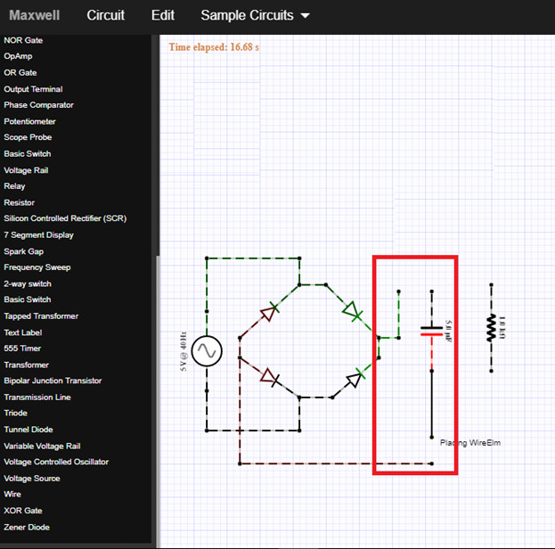
Now our final circuit diagram will look like this below.

Part II. How the circuit works
To analyze this circuit, let us divide the circuit or vary the circuit to explain it in details. First let us consider the original output of the bridge circuit. We must remove first the capacitor.

As you can see in the figure below, after we remove the capacitor, the oscilloscope displayed the full wave output of the bridge rectifier. This rectified output has a large AC component. We all know that the full wave rectifier will give an output signal, called the pulsating dc. It means there is an ac component of the signal. Our main goal is to have a smooth dc signal.
How does it work?
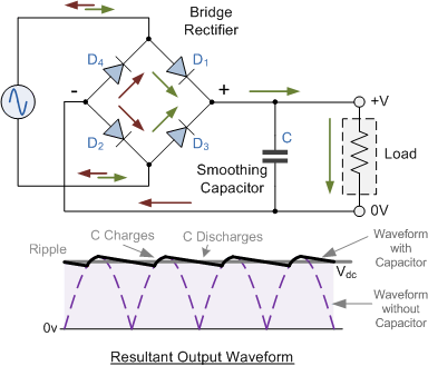
The filter capacitor converts the full wave rippled output signal from the bridge circuit into a smooth dc output signal. In general power supply, the aluminum electrolytic capacitor is commonly used but there are two significant parameters to be consider in choosing a capacitor for filtering purposes, these are the Working Voltage of the capacitor in which it should be higher than the no load output value of the rectifier and the Capacitance Value in which it determines the amount of ripple it can handle.
If the capacitor has a low capacitance value it has less effect in filtering out ac component but if it has a large value, then the output voltage will be as smooth as a pure dc signal.
The capacitor is used to store dc voltage only. So the main explanation here is that the capacitor will block any ac signal or no ac signal can pass through the capacitor. Only dc signal can pass through that is why at the output side, the only signal will be displayed is dc signal. But in this tutorial, we can see that the output signal is not a pure dc signal because it has a ripple or ac component.
Source

We used the capacitor filter to filter out unwanted signal or block the ac component of the output signal. The only signal that can be seen in the output side will be the dc signal. So let us connect the capacitor again.
As you can see in the output signal, it is a pulsating dc signal. This signal contains ripples. This ripple must be eliminated in the signal so that only dc signal will be displayed in the oscilloscope. You can add many filters at the output side to filter out the remaining ripples.

Part III. Circuit Simulation
For simulation, just click on the output terminal then connect it to the output node of the circuit as shown below.

Then click on the scope probe to display and connect the oscilloscope to the output terminal of the circuit. Then the oscilloscope will automatically display the output waveform as you can see in the figure.

You can adjust the output by dragging it downward or sideward it depends on your desired display.
After putting the filter capacitor parallel to the load resistor, the output signal will look like the figure below.

Same process in displaying the input signal in the oscilloscope, and it will look like this above. This is now the setup or the output signal after passing through the filter circuit.
Application
The readers can use the knowledge acquired from this tutorial creating a filter circuit for signal processing.
Curriculum
Here are my other tutorials for a circuit simulation of electronic circuits that may help you understands circuit operation.
Posted on Utopian.io - Rewarding Open Source Contributors
Your contribution cannot be approved because it does not follow the Utopian Rules.
You can contact us on Discord.
[utopian-moderator]
Hey @portugalcoin, I just gave you a tip for your hard work on moderation. Upvote this comment to support the utopian moderators and increase your future rewards!