Microcontroller Programming using MikroC & Proteus 8 professional: A step by step process in PIC programming of basic BCD decade counter and seven segment display
Hello everyone!
If you already read my first contribution and find it interesting, I hope for this second contribution of mine you will find it the same.
This is my second contribution, though my first contribution in the field of electronics and technology was pending for approval. I choose electronics and industry as my field of contribution because I find it more interesting like anyone does in our technology today. As the continuing growth of the electronics industry, we must adopt and know more about it in order for us to cope up with it.
Let’s start with the materials and software that we will be using in this topic
Materials
♦ Push button
♦ Capacitor
♦ Crystal oscillator
♦ Seven segment
♦ PIC16F84A
♦ Resistor
♦ 7448 IC
Software
◘ Proteus 8 professional
◘ MikroC compiler for PIC
Since we already know the materials that we need based from my first topic aside from seven segment and 7448 IC.
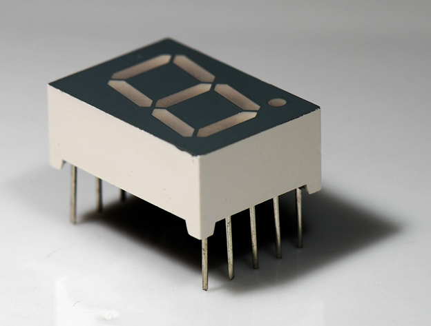
Seven Segment Display
A seven-segment display (SSD), or seven-segment indicator, is a form of electronic display device for displaying decimal numerals that is an alternative to the more complex dot matrix displays.
Seven-segment displays are widely used in digital clocks, electronic meters, basic calculators, and other electronic devices that display numerical information.
BCD or Decade Counter Circuit
A binary coded decimal (BCD) is a serial digital counter that counts ten digits .And it resets for every new clock input. As it can go through 10 unique combinations of output, it is also called as “Decade counter”. A BCD counter can count 0000, 0001, 0010, 1000, 1001, 1010, 1011, 1110, 1111, 0000, and 0001 and so on.
Decade Counter Operation
When the Decade counter is at REST, the count is equal to 0000. This is first stage of the counter cycle. When we connect a clock signal input to the counter circuit, then the circuit will count the binary sequence. The first clock pulse can make the circuit to count up to 9 (1001). The next clock pulse advances to count 10 (1010).
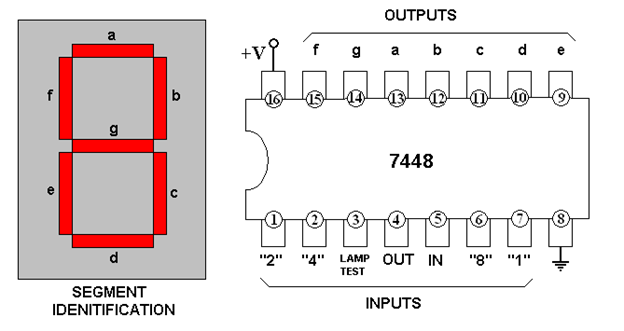
7448 BCD (Binary Coded Decimal) counter
Truth Table of Decade Counter
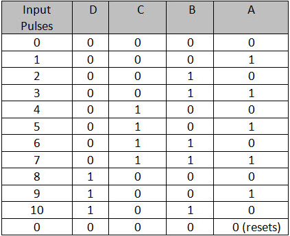
The above table describes the counting operation of Decade counter. It represents the count of circuit for decimal count of input pulses. The NAND gate output is zero when the count reaches 10 (1010).
The count is decoded by the inputs of NAND gate X1 and X3. After count 10, the logic gate NAND will trigger its output from 1 to 0, and it resets all flip flops.
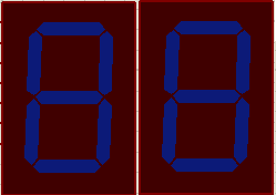
Desired Output Display
Pushbutton1
Increment of 1 (when press will count 1 to 9)
Pushbutton2
Increment of 2 (when press will add 2 to the least significant bit or the second seven segment (right), when it is more than 9 it will display zero and add 1 to the first seven segment)
Pushbutton3
Increment of 3 (when press will add 3 to the least significant bit or the second seven segment (right), when it is more than 9 it will display zero and add 1 to the first seven segment)
Pushbutton4
Increment of 5 (when press will add 5 to the least significant bit or the second seven segment (right), when it is more than 9 it will display zero and add 1 to the first seven segment)
Pushbutton5
Increment of 9 (when press will add 9 to the least significant bit or the second seven segment (right), when it is more than 9 it will display zero and add 1 to the first seven segment)
Part 1: MikroC compiler for PIC
Step 1. Open the MikroC software. Then click the “Project” button.
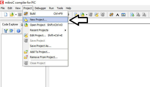
Step 2. Click the “New Project” for us to create our second tutorial.
Input our project name , example “rfeceTutor2”, project path is the folder path we like to save our project. The device we will use, the PIC16F84A. Check the necessary configuration as you can see in the picture below. Click “save” then click “ok”.
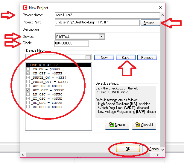
Step 3: New window will pop up. With the project name “rfeceTutor2”. In this window, we will program our codes. So here, I have created my own program. Programming is an art, so you can create or program with your own strategy. The shorter the codes the better, because it can only consume small memory size.
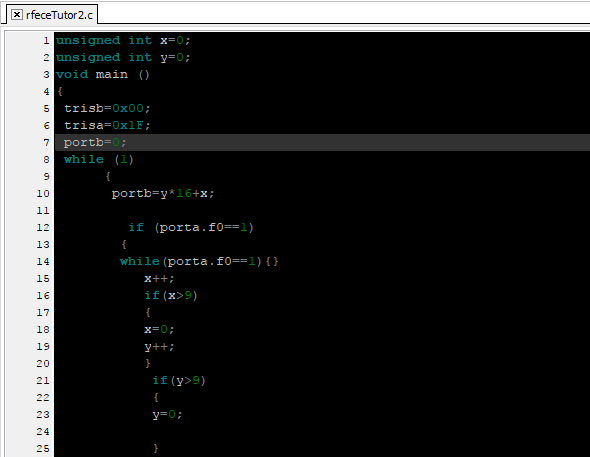
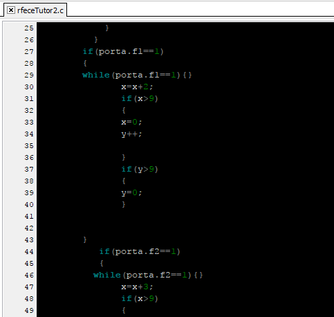
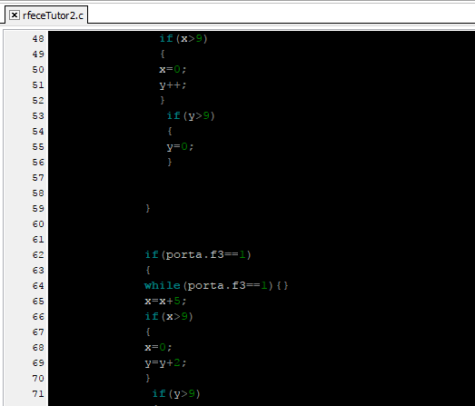
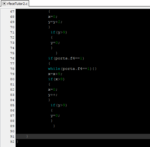
These are the codes that I had programmed for this session
unsigned int x=0;
unsigned int y=0;
void main ()
{
trisb=0x00;
trisa=0x1F;
portb=0;
while (1)
     {
      portb=y*16+x;

        if (porta.f0==1)
       {
       while(porta.f0==1){}
          x++;
          if(x>9)
          {
          x=0;
          y++;
          }
           if(y>9)
           {
           y=0;

           }
         }
       if(porta.f1==1)
       {
       while(porta.f1==1){}
              x=x+2;
              if(x>9)
              {
              x=0;
              y++;

              }
              if(y>9)
              {
              y=0;
              }


       }
          if(porta.f2==1)
          {
         while(porta.f2==1){}
              x=x+3;
              if(x>9)
              {
              x=0;
              y++;
              }
               if(y>9)
               {
               y=0;
               }


            }


            if(porta.f3==1)
            {
            while(porta.f3==1){}
            x=x+5;
            if(x>9)
            {
            x=0;
            y=y+1;
            }
             if(y>9)
             {
             y=0;
             }
               }
            if(porta.f4==1)
            {
            while(porta.f4==1){}
            x=x+9;
            if(x>9)
            {
            x=0;
            y++;
            }
             if(y>9)
             {
             y=0;
             }
              }

   }
}
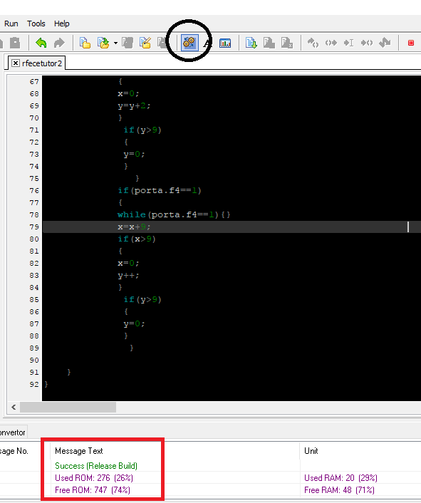
Step 4 : After coding, we will click “Build Project” to check if there are errors in our codes. As you can see below, “Success” it means our project was built and no errors in the program.
So now, we will burn this program to our PIC16F84A.
Part 2: Burning our project codes using the Proteus 8 Professional
Step 1: Open the proteus 8 professional software. Let us assume that we already created or constructed our circuit diagram
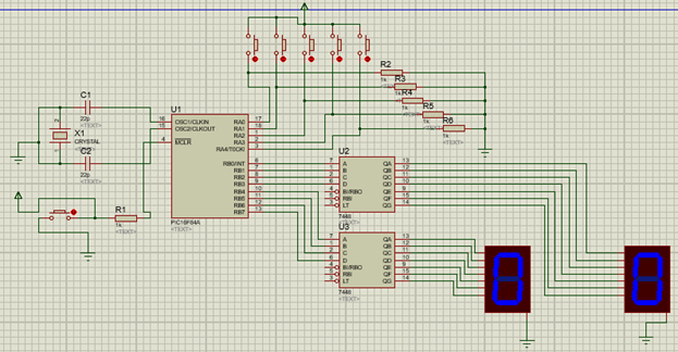
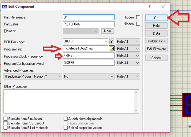
Step 2: Let’s burn the hex file or the code that we created in MikroC
Double click the PIC16F84A. The ”edit component” window will appear, we need to fill up the necessary component. For program file, it must be the hex file of the code that we created. Then click ok.
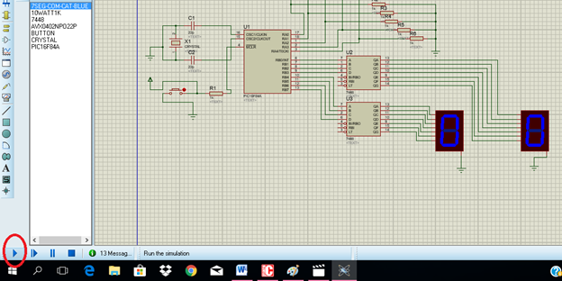
Step 3: Now let’s run our circuit. Click the run button below.
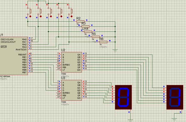
Step 4: Now let’s try if our desired output will be display in the seven segments.
Click each push button to see the output in the seven segment display.
Pushbutton 1
Pushbutton 2
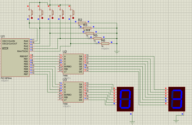
Pushbutton 3
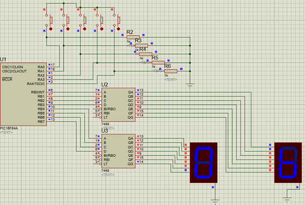
Pushbutton 4
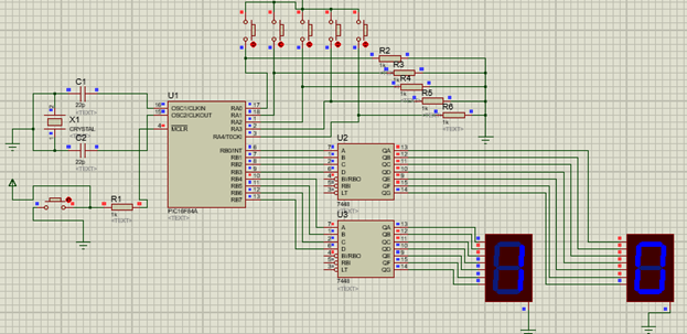
Pushbutton 5
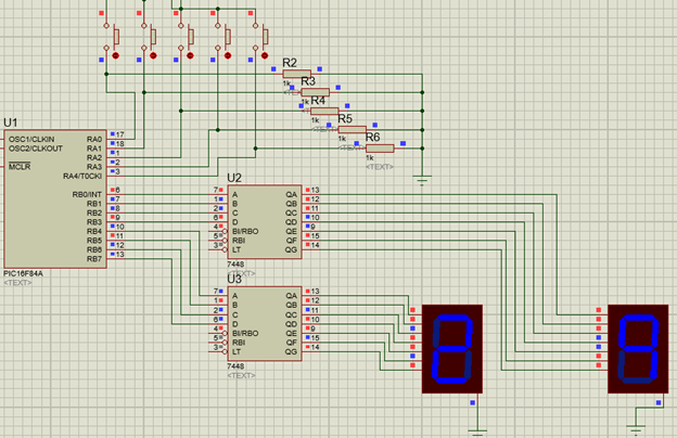
Conclusion
Now the desired output was achieved base from the simulation.
Application of this topic
In our everyday life we are using synchronous counter in all digital circuits which have timing in it. Suppose in the morning you will wake up with the help of alarm clock and digital watches that we used. Traffic light is a particular application of this session. Where it involves counting, display and timing of signals to be display. Each of us can create our own application.
The goal of education is not to increase the amount of knowledge but to create the possibilities for a child to invent and discover, to create men who are capable of doing new things.
--Jean Piaget
Wait for the next tutorial. Have a good day everyone.
God bless.
Thanks for dropping by!
Yours truly
Rfece143
Posted on Utopian.io - Rewarding Open Source Contributors
Thank you for the contribution. It has been approved.
You can contact us on Discord.
[utopian-moderator]
thank you @umais :-)
Hey @rfece143 I am @utopian-io. I have just upvoted you!
Achievements
Suggestions
Get Noticed!
Community-Driven Witness!
I am the first and only Steem Community-Driven Witness. Participate on Discord. Lets GROW TOGETHER!
Up-vote this comment to grow my power and help Open Source contributions like this one. Want to chat? Join me on Discord https://discord.gg/Pc8HG9x