Electronic Project 7: Starting the DC motor using the Force Sensitive Resistor
What Will I Learn?
At the end of this tutorial you will be able to:
♦ know how to start a dc motor using an FSR sensor.
♦ apply this mechanism in any related electronic projects.
♦ improve an existing electronic projects
Requirements
**Electronic Components **
♦ Arduino
♦ 5V relay
♦ 10k ohms Resistor
♦ Transistor
♦ 5V external supply (battery)
♦ 5V DC motor
♦ PCB
♦ Connecting wires
Software
♦ Fritzing application
Difficulty
-Advanced
Tutorial Contents
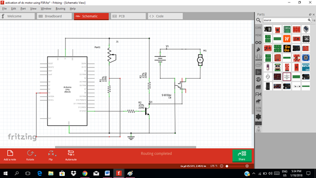
Using the fritzing software, we will create our circuit diagram, PCB layout and arduino codes.
Part I. Schematic Diagram
So first let us construct our circuit diagram.
- Open the fritzing software.
- Select the electronic components needed for the circuit in the fritzing library.
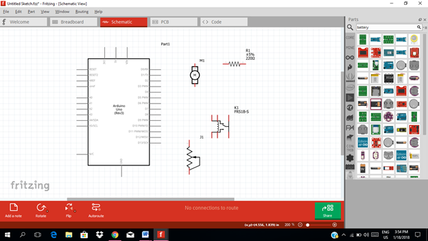
- Connect the circuit diagram.

- Connect the FSR to the 5v pin of the arduino uno.
The digital input pin number 13 will be connected to the input of the 5v relay as you can see in the figure below.
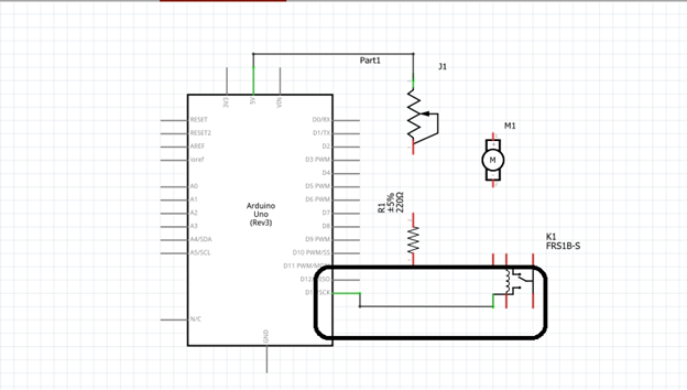
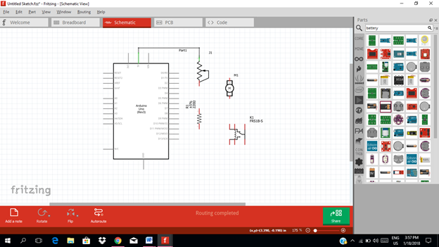
For the final circuit diagram

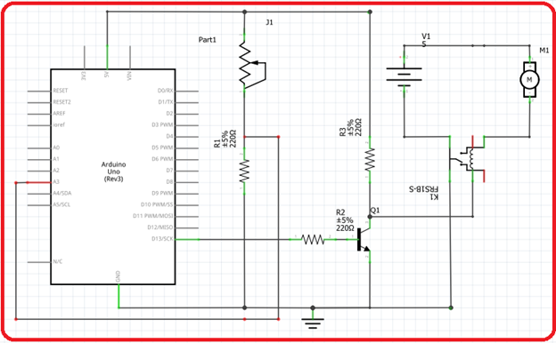


The force sensing resistor is an electronic component that changes its resistance when a force, pressure & mechanical stress are being applied. When a force is applied to the FSR, its resistance decreases and allowing current to flow.

This current is then fed to the analog input of the arduino and it is programmed to activate or to give output when the force sensing resistor triggers. The digital output is then fed to the base resistor of the transistor. This transistor will act as a switch. Allowing a current output at the collector terminal.

This current output from the transistor is then fed to the 5V relay. The relay will trigger, switching the battery to connect to the dc motor making it to activate.

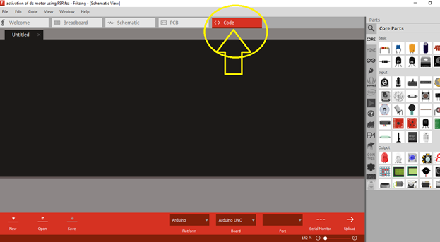
Part II. Code
Now let us do programming of our Arduino uno.
Click on code to start.
So in our code, we take consideration that our input signal will be based on the functionality of the force sensitive resistor.
We will choose which analog pin input do we use, so in this tutorial I will use pin number 3 (Analog input). The digital output (pin number 13) is connected to the base resistor of the transistor’s input.

int fsrsensorPin = 3;
int baseresistorPin = 13;
int fsrsensorValue = 0; // variable to store the value coming from the FSR sensor

void setup()
{
pinMode(baseresistorPin, OUTPUT); // declare the baseresistorPin as an OUTPUT:
}

void loop()
{
fsrsensorValue = analogRead(fsrsensorPin); // read the value from the FSR sensor:
digitalWrite(baseresistorPin, HIGH); // turn the transistor’s baseresistorPin on
delay(fsrsensor500); // stop the program for milliseconds:
digitalWrite(baseresistorPin, LOW); // turn the transistor’s baseresistorPin off:
delay(fsrsensor1000ms); // stop the program for milliseconds:
}

Now this is our Arduino Codes
int fsrsensorPin = 3;
int baseresistorPin = 13;
int fsrsensorValue = 0;
void setup() {
pinMode(baseresistorPin, OUTPUT);
}
void loop() {
fsrsensorValue = analogRead(fsrsensorPin);
digitalWrite(baseresistorPin, HIGH);
delay(fsrsensor500ms);
digitalWrite(baseresistorPin, LOW);
delay(fsrsensor1000ms);
}
Part III. PCB Layout
Click on the PCB.

Arrange or design your circuit on the pcb.

Click on the autoroute to enable the autoconnect for the circuit layout.

Drag the connection according to your layout.

Now let us design our circuit layout on the PCB.

Application
The user can use the output part of the circuit to control the lights when the FSR sensor is being pressed or touch. And also you can make your own electronic projects that need a force sensitive resistor to control the output.
The link below is an example of FSR used in controlling led lights.
Curriculum
Here are my other tutorials for electronic projects.
**ELECTRONIC PROJECTS **
Posted on Utopian.io - Rewarding Open Source Contributors
Thank you for the contribution. It has been approved.
You can contact us on Discord.
[utopian-moderator]
thanks @forkonti :-)
Hey @forkonti, I just gave you a tip for your hard work on moderation. Upvote this comment to support the utopian moderators and increase your future rewards!
good writing I like. expand the work again, and more articles. hopefully a little science that you provide useful to the reader
do not forget to follow me @amirdesaingrafis
greetings follow me and follow me. thank you
super greetings @amirdesaingrafis
thanks @amirdesaingrafis ..sure..next time..
A great tutorial for beginners to follow, I used to use Proteus software to design my circuits but this one looks more advanced.
wow..thanks @aamirijaz ..i guess you like electronics..
Hey @rfece143 I am @utopian-io. I have just upvoted you!
Achievements
Suggestions
Get Noticed!
Community-Driven Witness!
I am the first and only Steem Community-Driven Witness. Participate on Discord. Lets GROW TOGETHER!
Up-vote this comment to grow my power and help Open Source contributions like this one. Want to chat? Join me on Discord https://discord.gg/Pc8HG9x