Electronic Project 41: Automatic Water Level Indicator & Alarm System using transistor and arduino uno
What Will I Learn?
At the end of this tutorial:
♦ You will be able to learn the three major function of this application, the schematic feature, code window for programming the microcontroller and prototyping in breadboard
♦ The readers will be able to create a water level indicator and alarm system when the tank is already full of water using the transistor and arduino uno as the microcontroller.
♦ The readers will be able to know how a water level indicator and alarm system works upon adding water to a tank or any container
♦ Learn to apply the circuit in creating advance technology in the future electronic projects
Introduction
Today, we suffered the climate change or the global warming, the rise in the average temperature of the earth’s climate system that is why we really need water conservation. We cannot afford to waste water anymore because water is essential to all living things in order to live. The purpose of this project is to help us conserve and avoid wasting water.
The common problem is the water tank overflow which leads to wastage of water. This project aims to give a water level indicator using led and a sound alarm when the tank is already full that’s the time the water supply must be cut off to avoid wastage of water.

Requirements
Electronic Components
♦ Arduino Uno
♦ Transistor (BC548 NPN)
♦ Piezo buzzer (5V)
♦ LED (green, yellow & red)
♦ Generic Female header (water contact)
♦ Resistor (6pcs. -2.2 Kilo ohms & 6pcs. -100 ohms)
♦ Switch button (SPST)
♦ Breadboard
♦ Connecting wires
Software
♦ Fritzing application
Difficulty
♦ Advance
Tutorial Contents
Using the fritzing software, we will create our circuit diagram, arduino codes and prototype using the breadboard
Part I. Schematic Diagram
So first let us construct our circuit diagram.
Select the electronic components needed for the circuit in the fritzing library. We need 1 arduino uno, 12 resistors, 1 piezo buzzer , 6 transistors, 3 LEDs, 1 switch and 4 generic female header for water contact.
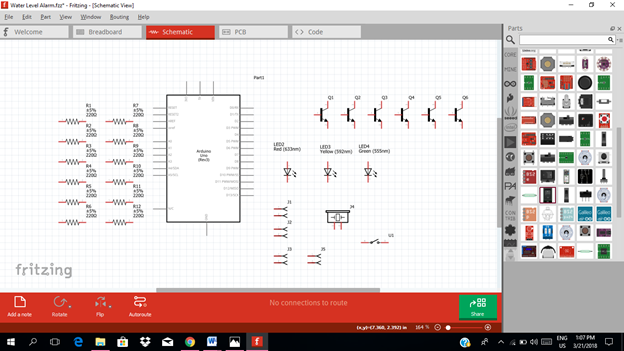
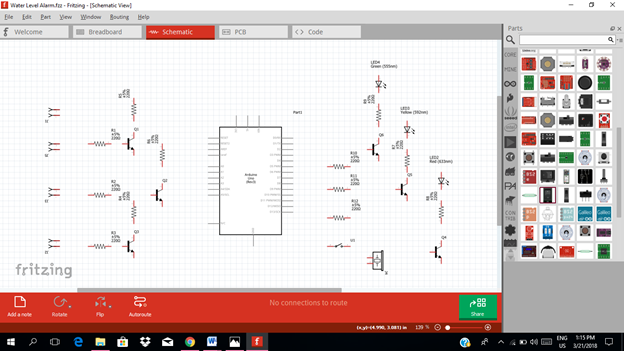
Arrange the components before constructing the circuit.
In arranging the components, place all the components for the input side (left side) of the arduino and the components for the output side (right side).
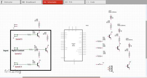
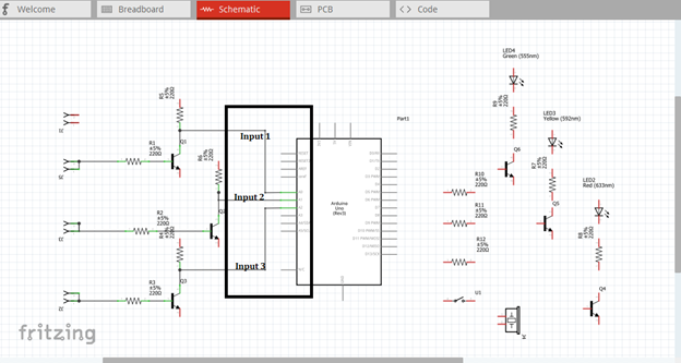
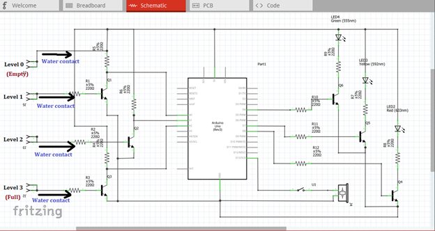
In the input side of our circuit, we need to construct three transistors that will act as switch and we need also three triggering contact which is the generic female header. The moment it touches the water, it will trigger the transistor switch.
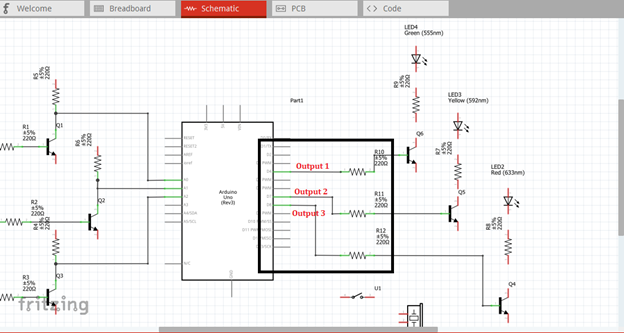
While in the output side of our circuit, we have three transistor circuit that act as an amplifier circuit. The output of this amplifier will be connected to the light indicator. We have also the sound alarm signal from the buzzer that will be connected to another output pin of the arduino uno.
Now let us construct our circuit diagram. We will connect the water contact pin to the base resistor of each transistor as the triggering component as shown in the figure below. This generic female header must be placed inside the container or tank so that when there is water it will directly touch the water as it reach its corresponding level.
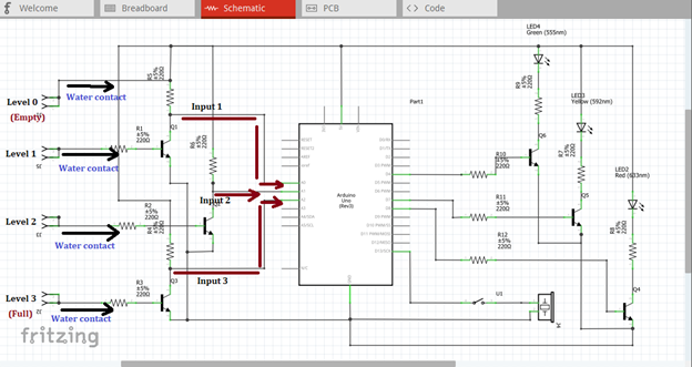
Then the output of each transistor at the collector terminal will be connected to the three input pins of our microcontroller. Here we use analog pin A0, A1 & A2. These three inputs will trigger the arduino uno to give an output signal based from the programmed codes.
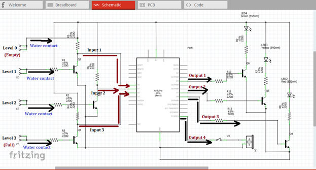
The three outputs, pin 4, 7 & 8 must be connected to the base resistor of the amplifier circuit to be amplified so that it can drive the light indicator. The output signal at pin 13 will be connected to the switch button and then to the buzzer alarm.
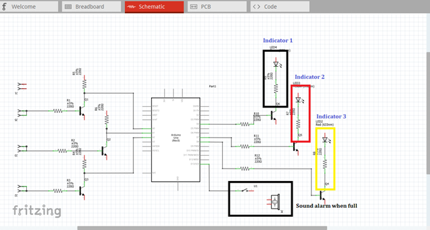
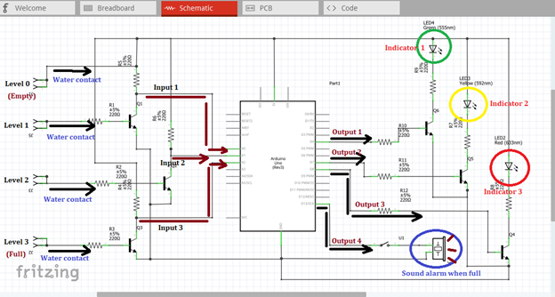
The amplified output of each amplifier circuit will be connected to each level indicator in which water can possibly reached. The indicator will only give lights if the water level reach or touch the water contact being placed inside the container or tank. Then a sound alarm will be heard if the tank is already full or the water level reach the highest peak or level in which the water contact was placed.
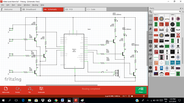
Now this is our final circuit diagram.
Theory of operation:
In our circuit, we have four metal or water contacts that were placed inside the tank. When the tank is empty, no indicator will be displayed, that is the level 0 indicator. The tank is being labeled into three, level 1, level 2 & level 3. Level 3 indicates that the tank is full, while level 1 & 2 indicates the tank is half full and three fourths full. When these three contacts touch the water, it will trigger the switch. Then the switch will give an output signal at the collector terminal.
These outputs at the collector terminal will now act as the input signal of our microcontroller. The moment it flows through the input pins of the microcontroller, an output signals will be seen at the four pins of the microcontroller, pin 4, 7, 8 & 13 based from the programmed arduino codes.
The first three output signals will be the input signal of the three amplifier circuits. These signals will be amplified so that it can drive the light indicator in each water tank level. The fourth output signal as shown below will drive the buzzer alarm when the tank is full or the water level reached the highest water contact level.
Now you will see the green light indicator when the water level reach the first water contact, then yellow light indicator when water level reach the second water contact and red light indicator when the water level reach the highest water contact that was placed at the top of the container or tank. At the same time a sound signal will be heard when the water reach this level.
Part II. Code
Now let us do programming of our Arduino uno.
Click on code to start.
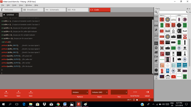
The input pin for our microcontroller from the output of each transistor switch circuit is pin A0, A1 & A2. While the output pins of our circuit will be the pin 4, 7, 8 & 13.
int in1Pin = 0;  //output at transistor switch 1 as input 1
int in2Pin = 1;  // output at transistor switch 2 as input 2
int in3Pin = 2;  // output at transistor switch 3 as input 3
int out1Pin = 4; //output pin for green light indicator
int out2Pin = 7; //output pin for yellow light indicator
int out3Pin = 8; //output pin for red light indicator
int out4Pin = 13; //output pin for sound alarm

void setup() {
pinMode (in1Pin, INPUT);        //switch 1 as input signal 1
pinMode (in2Pin, INPUT);        //switch 2 as input signal 2
pinMode (in3Pin, INPUT);        //switch 3 as input signal 3
pinMode(out1Pin, OUTPUT);   //for green led
pinMode(out2Pin, OUTPUT);   //for yellow led
pinMode(out3Pin, OUTPUT);   //for red led
pinMode(out4Pin, OUTPUT);   //for the buzzer
}
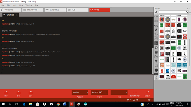
void loop(){
if(in1Pin >=threshold){
digitalWrite(out1Pin, HIGH); //give output at pin 4 to be amplified at the amplifier circuit
else
digitalWrite(out1Pin, LOW); //no output at pin 4
}
if(in2Pin >=threshold){
digitalWrite(out2Pin, HIGH); //give output at pin 7 to be amplified at the amplifier circuit
else
digitalWrite(out2Pin, LOW); //no output at pin 7
}
if(in3Pin >=threshold){
digitalWrite(out3Pin, HIGH); //give output at pin 8 to be amplified at the amplifier circuit
digitalWrite(out4Pin, HIGH); //give output at pin 13 to drive the buzzer

else
digitalWrite(out3Pin, LOW); //no output at pin 8
digitalWrite(out4Pin, LOW); //no output at pin 13
}
}
Here are our arduino codes.
int in1Pin = 0;  //output at transistor switch 1 as input 1
int in2Pin = 1;  // output at transistor switch 2 as input 2
int in3Pin = 2;  // output at transistor switch 3 as input 3
int out1Pin = 4; //output pin for green light indicator
int out2Pin = 7; //output pin for yellow light indicator
int out3Pin = 8; //output pin for red light indicator
int out4Pin = 13; //output pin for sound alarm
void setup() {
pinMode (in1Pin, INPUT);        //switch 1 as input signal 1
pinMode (in2Pin, INPUT);        //switch 2 as input signal 2
pinMode (in3Pin, INPUT);        //switch 3 as input signal 3
pinMode(out1Pin, OUTPUT);   //for green led
pinMode(out2Pin, OUTPUT);   //for yellow led
pinMode(out3Pin, OUTPUT);   //for red led
pinMode(out4Pin, OUTPUT);   //for the buzzer
}
void loop(){
if(in1Pin >=threshold){
digitalWrite(out1Pin, HIGH); //give output at pin 4 to be amplified at the amplifier circuit
else
digitalWrite(out1Pin, LOW); //no output at pin 4
}
if(in2Pin >=threshold){
digitalWrite(out2Pin, HIGH); //give output at pin 7 to be amplified at the amplifier circuit
else
digitalWrite(out2Pin, LOW); //no output at pin 7
}
if(in3Pin >=threshold){
digitalWrite(out3Pin, HIGH); //give output at pin 8 to be amplified at the amplifier circuit
digitalWrite(out4Pin, HIGH); //give output at pin 13 to drive the buzzer
else
digitalWrite(out3Pin, LOW); //no output at pin 8
digitalWrite(out4Pin, LOW); //no output at pin 13
}
}
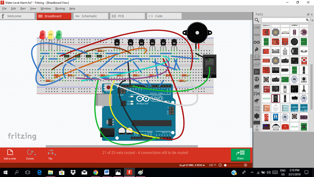
Part III. Breadboard
Click on the breadboard.
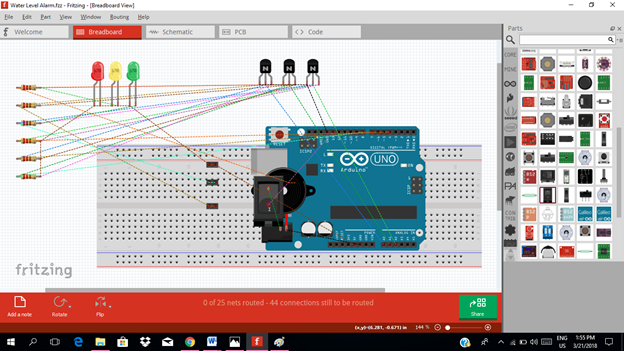
Arrange each component in the breadboard before connecting.
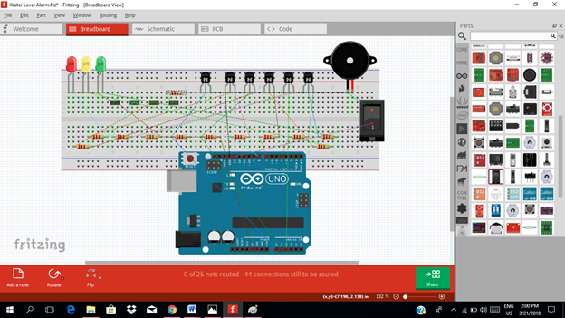
Now connect each component if you don’t know how to connect using breadboard just read my previous tutorial about how to construct a circuit in the breadboard
Application
The readers can apply this project in:
♦ water level monitoring
♦ irrigation control
♦ high or low water level alarms
Like the example below.
Curriculum
Here are my other tutorials for electronic projects.
ELECTRONIC PROJECTS
Posted on Utopian.io - Rewarding Open Source Contributors
Your contribution cannot be approved because it does not follow the Utopian Rules.
Violated Rule(s):
My Opinion(s):
You can contact us on Discord.
[utopian-moderator]
Hey @yokunjon, I just gave you a tip for your hard work on moderation. Upvote this comment to support the utopian moderators and increase your future rewards!
Congratulations @rfece143! You have completed some achievement on Steemit and have been rewarded with new badge(s) :
Click on any badge to view your own Board of Honor on SteemitBoard.
For more information about SteemitBoard, click here
If you no longer want to receive notifications, reply to this comment with the word
STOP