Electronic Project 40: A Metal Detector for Security Device using the principle of a tank circuit for inductive sensing and with the aid of op-amp, speaker and arduino uno
What Will I Learn?
At the end of this tutorial:
♦ The readers will be able to create a security device system where a metal detecting device is applied that aims to provide more secure environment where safety is the most important.
♦ The readers will be able to know how the tank circuit works and how it detects nearby metals based from the theory of operation.
♦ Learn to apply the device in a security system and to innovate existing security measures in the future electronic projects
Introduction
Metal detectors were first invented by German Physicist Heinrich Wilhelm Dove and it was known as the induction balance, an electromagnetic metal-locating device. This device was used to locate the bullet that was stock in the body of US President James A. Garfield after he was shoot in july 1881.
Today, metal detectors aren’t just used in finding jewelries but they are mainly used in airports walk through scanners so that they can stop anyone from carrying guns or deadly weapons for security purposes.
You can read more about the history of metal detectors here.
Requirements
Electronic Components
♦ Arduino Uno
♦ Speaker
♦ Capacitor
♦ Inductor
♦ Diode
♦ Op-amp
♦ Resistor
♦ Breadboard
♦ Connecting wires
Software
♦ Fritzing application
Difficulty
♦ Advance
Tutorial Contents
Using the fritzing software, we will create our circuit diagram, arduino codes ,prototype using the breadboard and PCB layout.
Part I. Schematic Diagram
So first let us construct our circuit diagram.
Select the electronic components needed for the circuit in the fritzing library. We need 1 arduino uno, 1 speaker, 5 resistors, 1 capacitor, 1 inductor, 1 transistor, 1 op-amp, 1 diode and 1 LED.
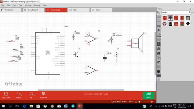
Arrange the components before constructing the circuit.
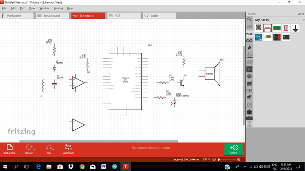
In arranging the components, place all the components for the input side (left side) of the arduino and the components for the output side (right side).
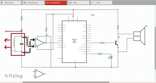
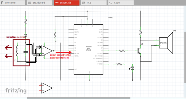
At the input side of our circuit we have the tank circuit that is compose of inductor and capacitor that will be connected in parallel. Then we have an operational amplifier circuit that will amplify the signal before connecting to the input of the microcontroller. While at the output side of our circuit, we have the speaker for the sound alarm and a led for light signal and an amplifier circuit.
Now let us construct our circuit diagram. The tank circuit is the parallel connection between capacitor and inductor. It is called a tank circuit because it can store energy oscillating at the circuit’s resonant frequency. This circuit can act as electrical resonator, known as resonant circuit.
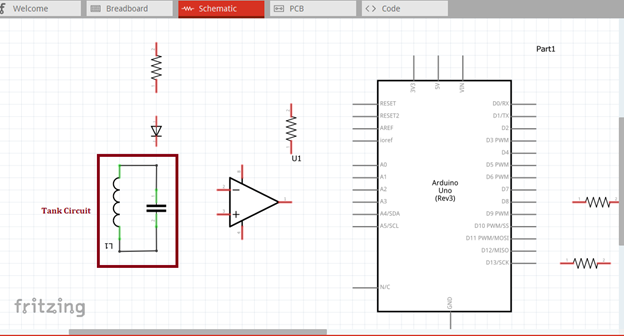
Then the tank circuit must be connected to the operational amplifier inputs as shown in the figure below. Then the tank circuit also connected to the diode to allow the current to flow in only one direction.
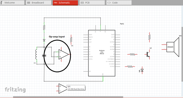
Then we connect the output of the op-amp to the analog input of the microcontroller, which we use analog pin 3. There is no feedback component in the op-amp circuit it will only give amplified output when the tank circuit detects metal object.
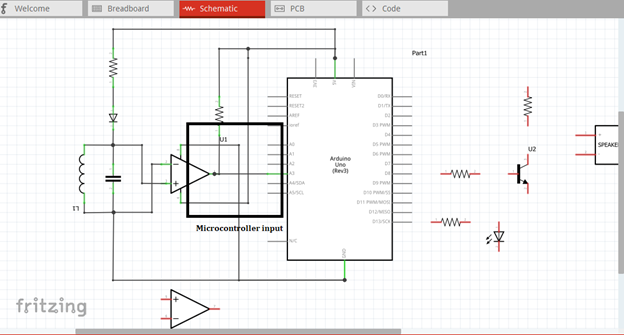
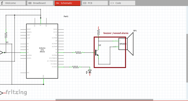
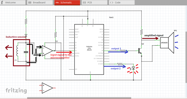
Then at the output side of our microcontroller, we have to connect the two outputs to the two external alarm circuits. One for the speaker and one for the led light.
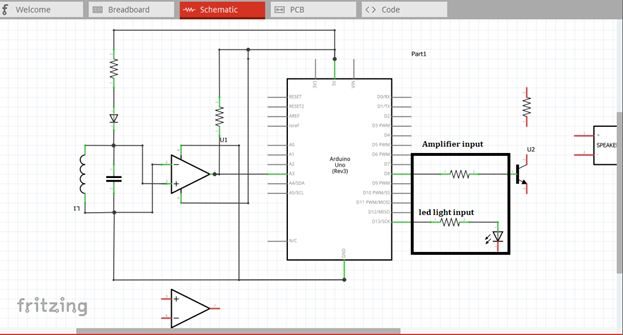
As you can see in the figure shown below, the amplified output signal at the collector terminal is being connected to the speaker directly, this will allow speaker to trigger when metal is detected.
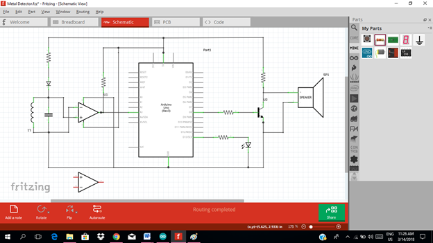
Now this is our final circuit diagram.
Theory of operation:
If an inductor is connected in parallel with a charged capacitor, current will start to flow through the inductor, building up a magnetic field around it and reducing the voltage on the capacitor.
Finally all the charge on the capacitor will be gone and the voltage across it will reach zero. However, the current will continue, because inductors resist changes in current. The current will begin to charge the capacitor with a voltage of opposite polarity to its original charge.
According to faraday’s law, the electromotive force which drives the current is caused by a decrease in the magnetic field, thus the energy required to charge the capacitor is extracted from the magnetic field.
When the magnetic field is completely dissipated the current will stop and the charge will again be stored in the capacitor, with the opposite polarity as before. Then the cycle will begin again, with the current flowing in the opposite direction through the inductor. The magnetic field that being stored in the inductor is used to detect the presence of metal, like magnet attract metals.
When there is a metal, it will be attracted by the magnetic field that being stored in the inductor. A signal will flow at the input of the op-amp circuit for amplification.
This output signal from the op-amp is then fed to the input of the microcontroller. That’s the time our microcontroller will be triggered and then it will give an output signals at pin 8 & 13.
The output at pin 8 is being connected to the base resistor of the transistor to be amplified once again in order to drive the speaker at the collector terminal. While the output signal at pin 13 is directly connected to the resistor in series with the led.
Part II. Code
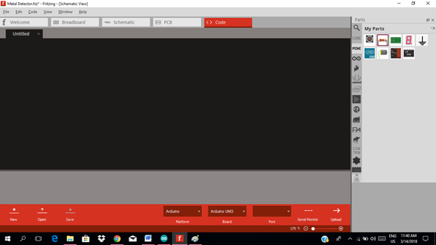
Now let us do programming of our Arduino uno.
Click on code to start.
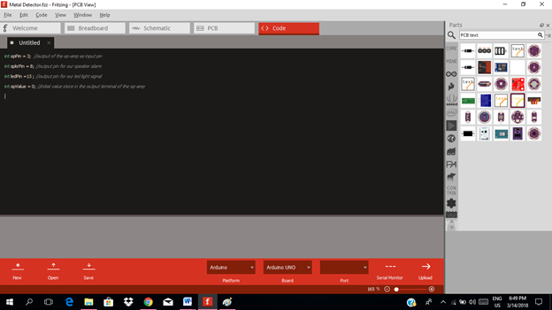
The input pin for our microcontroller from the output of the light sensor is the analog pin 3 and the output pin is pin 13.
int opPin = 3;  //output of the op-amp as input pin
int spkrPin = 8; //output pin for our speaker alarm
int ledPin =13 ; //output pin for our led light signal
int opValue = 0; //initial value store in the output terminal of the op-amp
void setup()
{
pinMode(opPin,INPUT); //op-amp as input pin
pinMode(spkrPin,OUTPUT); //output pin at speaker
pinMode(ledPin,OUTPUT);  //output pin at led
}

void loop()
{
opValue =analogpin(opPin); //read the value at the op-amp output
if(opValue>=threshold){
digitalWrite(spkrPin,HIGH); //give output signal at pin 8
delay(1000);
digitalWrite(ledPin,HIGH); //give output signal at pin 13
delays(1000);
else {
digitalWrite(spkrPin,LOW); //no output at pin 8
digitalWrite(ledPin,LOW); }//no output at pin 13
}
}

Here are our arduino codes.
int opPin = 3;  //output of the op-amp as input pin
int spkrPin = 8; //output pin for our speaker alarm
int ledPin =13 ; //output pin for our led light signal
int opValue = 0; //initial value store in the output terminal of the op-amp
void setup()
{
pinMode(opPin,INPUT); //op-amp as input pin
pinMode(spkrPin,OUTPUT); //output pin at speaker
pinMode(ledPin,OUTPUT);  //output pin at led
}
void loop()
{
opValue =analogpin(opPin); //read the value at the op-amp output
if(opValue>=threshold){
digitalWrite(spkrPin,HIGH); //give output signal at pin 8
delay(1000);
digitalWrite(ledPin,HIGH); //give output signal at pin 13
delays(1000);
else {
digitalWrite(spkrPin,LOW); //no output at pin 8
digitalWrite(ledPin,LOW); }//no output at pin 13
}
}
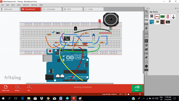
Part III. Breadboard
Click on the breadboard.
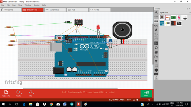
Arrange each component in the breadboard before connecting.
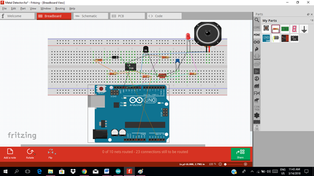
Now connect each component if you don’t know how to connect using breadboard just read my previous tutorial about how to construct a circuit in the breadboard

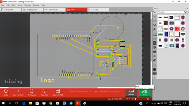
Part IV. PCB Layout
Click on the PCB window.
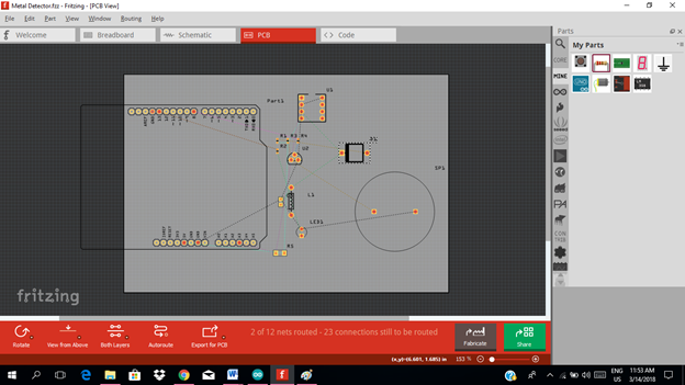
In connecting the circuit in the PCB you can choose either manual connection or automatic routing connection.
In manual connection you will connect each pin manually by clicking the pin & drag and connect to the other pin. In this tutorial we will use the manual layout.
But before connecting each pin, we can arrange each component for a better layout.
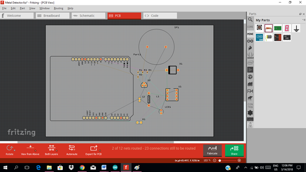
Now we can start making our layout by following the wire connection.
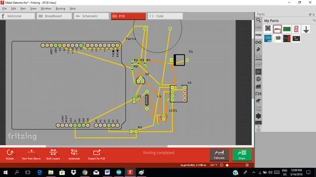
In automatic connection, you will just click on autoroute to automatically connect the circuit base from the circuit diagram.
After that, you can design your pcb by dragging the connection according to your desired design. For this tutorial, this my sample pcb layout for this metal detector circuit.
Application
The readers can create their own metal detecting device for security purposes or for other important application. See the example link below.
Curriculum
Here are my other tutorials for electronic projects.
ELECTRONIC PROJECTS
Posted on Utopian.io - Rewarding Open Source Contributors
Thank you for the contribution. It has been approved.
You can contact us on Discord.
[utopian-moderator]
thanks @portugalcoin
Nice threads sir! I'm an ECE graduate too and an electronics enthusiast. Was trying to check if I could see and interact with the field here in steemit. Keep posting! :)
wow..nice to hear that you are an ECE....im pretty sure you have a lot of electronic projects...you can be a great contributor for an open source project as well
Yes sir, i've got lots of projects too. Just that, im still having second thoughts on posting itdirectly in here.
Hey @rfece143 I am @utopian-io. I have just upvoted you!
Achievements
Community-Driven Witness!
I am the first and only Steem Community-Driven Witness. Participate on Discord. Lets GROW TOGETHER!
Up-vote this comment to grow my power and help Open Source contributions like this one. Want to chat? Join me on Discord https://discord.gg/Pc8HG9x